D
Deleted member 550749
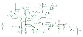
Sorry for not updating the final schematic, this the sch which m using and made-


H
HAYK
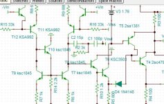
I suggest you replace the VAS 5551 to ksc3503 and its CCS BD140 to KSC1381.
How did you know the VAS current to be 1ma?
The C5200 is the king of power transistors, don't look for better
How did you know the VAS current to be 1ma?
The C5200 is the king of power transistors, don't look for better
Last edited by a moderator:
The C5200 might very well make that circuit sound as good as you can make it sound. But I wouldn’t call it the KING of power transistors. Its predecessor was better.
D
Deleted member 550749
1ma I checked , that's actually 1.05ma with 1.2volt and output from bd139 emitter 620mv+55ma for power transistor, working very cool without any distortion,
D
Deleted member 550749
Better transistor mean more costly, by the way I'm using ttc5200 30mhz is enough for me , may b 40mhz trnsister will b best but it's ok for me😉
H
HAYK
The VAS stage needs high impedance (high early) and low Cob to get high gain up to high frequencies. My personal choice is what Pionner used is 2sa1145 2sc2705, but it is obsolete although widely available.
If you stay with 5551, make the CCS 5401, BD doesn't make sense.
If you stay with 5551, make the CCS 5401, BD doesn't make sense.
D
Deleted member 550749
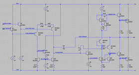
The LM3886 equivalent circuit has a phase inversion problem on the negative clipping because the VAS current is not limited, but I would be very surprised if that problem actually exists on real chips. It can be fixed with a Baker clamp or a collector resistor on the Darlington transistor, or a transistor or diode current limit using the 800 Ohm Re. If anyone has an LM3886, I'd like to see the clipping waveform? Also, has TI fixed their spice model? It has/had serious problems. Others here in DIYA have made models based on the "equivalent circuit", ie in the LTC Spice thread.
Fun project but I can't help but wonder why it exists. The LM3886 is a pretty standard Linn architecture with a few tweaks and NPN-only output stage (because PNPs in the process are awful). You could design a better amp if you used a complimentary Class AB output stage. I'd also be a bit careful with the diode biasing of the output stage in a discrete circuit. You do want reasonably good thermal tracking to prevent thermal runaway. That said, it looks like a fun learning exercise.
The LM3886 has a few protection circuits built in that aren't shown in the equivalent circuit schematic, including:
You also seem to have dropped the mute circuit. 😉
I have never seen phase reversal on an LM3886. It does suffer from a bit of rail sticking and spurious oscillation when it exits rail sticking on the positive rail. That can be mitigated by the Rf2, Cf, and Cc shown in AC Test Circuit #2 in the LM3886 data sheet. If you treat it right, the LM3886 works very well.
Tom
The LM3886 has a few protection circuits built in that aren't shown in the equivalent circuit schematic, including:
- Over-temperature protection
- Over-current protection
- SOA protection
You also seem to have dropped the mute circuit. 😉
I have never seen phase reversal on an LM3886. It does suffer from a bit of rail sticking and spurious oscillation when it exits rail sticking on the positive rail. That can be mitigated by the Rf2, Cf, and Cc shown in AC Test Circuit #2 in the LM3886 data sheet. If you treat it right, the LM3886 works very well.
Tom
D
Deleted member 550749
Yes, i just made for fun, removed mute cirquit to make it more simple , when I first made with bootstrap version, there was very bad clipping distortion happened that was very bad, after coming here someguys r helped to improve the circuit, made this just because in India u can't find a original ic and if u find that's double or triple price, and diy is best it can take huge place on PCB but repairable, and I can tweak, modify for high voltage for more power 👍 fun project, working satisfied 😉
Boring... Folded cascode , hawksford , CFA ... "self clamping VAS"The LM3886 is a pretty standard Linn architecture
H
HAYK
I did remember I had analyzed the LM3886 once upon a time. Beginners find this circuit noting but ordinary quasi complimentary without noticing the extra NPN driver in negative pole.
The DS if someone reads carefully says, if amplifiers are concidered to be class B, this amp is class AB. Here is why look bellow the output transistors currents, the positive rail one is non switching.

By then I had found that adding 680K resistor in parallel to 10pF makes it better.I don't remember why.
The DS if someone reads carefully says, if amplifiers are concidered to be class B, this amp is class AB. Here is why look bellow the output transistors currents, the positive rail one is non switching.
By then I had found that adding 680K resistor in parallel to 10pF makes it better.I don't remember why.
Attachments
Last edited by a moderator:
H
HAYK
Dear sir how does it sound?Sorry for not updating the final schematic, this the sch which m using and made- View attachment 1208931
D
Deleted member 550749
Last used 2or 3 month ago, only tried to fix negetive clipping, fixed but that diod remove is wrong dicision reverted working, but I got better circuit of this same IC that's without diod version, currently using honeybadger sounds good or better than this 🤣🤣 LM
Attachments
- Home
- Amplifiers
- Solid State
- LM3886 internal Schematic build or reverse engineering circuit