I was wondering if using the LM3886 in a differential (inverting) topology would be a good way to kill ground loops. I say inverting because that way the signal ground doesn't even get referenced to power ground except through the chip. Any thoughts on this? Am I wasting my time?
Don't have a ground loop in the first place would be the answer or use a balanced line input with the ground lifted. In the PA world we call it a DI unit.
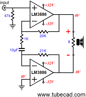
My concern is more from a safety aspect, since I want to earth my PS ground, but even doing so through a 5R6 gives me some ground loop noise at full volume when driven by a laptop with a cheap SMPS. If I set up the LM3886 in differential mode, as in :

Signal ground connected to V1
signal + connected to V2
That way there wouldn't be any connection, except through the actual opamp itself, between the signal ground and the power ground, completely breaking the ground loop.
Signal ground connected to V1
signal + connected to V2
That way there wouldn't be any connection, except through the actual opamp itself, between the signal ground and the power ground, completely breaking the ground loop.
Last edited:
On second thoughts, that isn't inverting. However, even if it was inverting (signal ground to V2, signal+ to V1) it would still benefit from the R2 and Rg being in the ground-loop path, and those would be several orders of magnitude larger than the 5R6 I am using to break the ground loop currently.
is conventional unbalanced non-inverting.Signal ground connected to V1
signal + connected to V2......
It is not differential, because you have some parts connected to ground.
My concern is more from a safety aspect, since I want to earth my PS ground, but even doing so through a 5R6 gives me some ground loop noise at full volume when driven by a laptop with a cheap SMPS. If I set up the LM3886 in differential mode, as in :
Signal ground connected to V1
signal + connected to V2
That way there wouldn't be any connection, except through the actual opamp itself, between the signal ground and the power ground, completely breaking the ground loop.
Mmmmmhhhh, that is a differential amplifier, which will reject common mode noise, useful if you have a weak signal through a long cable , as in balanced microphone preamp.
On this case , "balanced" is audio/oldspeak for techspeask "differential", the principle is the same.
Now, if you have *local* grounding problems at the LM3886, that's another problem, solved by better layout at the amp.
A different solution for a different problem.
And as Andrew pointed: if you have an already noisy and unbalanced signal coming from a notebook or whatever, this will not solve any of that.
In fact, this will *faithfully* reproduce your dirty signal

That will work well IF:If I set up the LM3886 in differential mode, as in :
Signal ground connected to V1
signal + connected to V2
1) R1 = R2
2) Rf = Rg
3) Bottom of Rg is connected to power ground (or whatever the speaker return is connected to)
4) and finally the hard part: The source impedance seen by V1 and V2 must be equal.
e.g. If V1 is directly connected to signal ground, but V2 is connected to
signal + via a volume pot, it won't work. Similarly, if there's a coupling cap between the source and V2, there needs to be an equal coupling cap between V1 and signal ground.
The easiest way to stupid-proof it is to put a unity gain buffer between input signal and V2. That makes it immune to variations in source impedance.
The problem isn't the source, the problem is a ground loop. I can get rid of it by disconnecting my amp's PS ground from the mains earth, but that can be dangerous in fault conditions. I can also get rid of it by unplugging my laptop SMPS, but that only lasts until the battery dies. Because the voltage drop which causes the distortion is caused by the V=RI drop in the input cable due to the circulating currents on the ground line but not the signal line, I was thinking that by using a topology which doesn't connect the ground of the signal line to the ground of the amp power supply might fix the problem.JMFahey said:And as Andrew pointed: if you have an already noisy and unbalanced signal coming from a notebook or whatever, this will not solve any of that.
Absolutely, that was what I was planning. I should have made that more clear.godfrey said:That will work well IF:
1) R1 = R2
2) Rf = Rg
3) Bottom of Rg is connected to power ground (or whatever the speaker return is connected to)
Ah, I knew I was missing something, the moment I add a pot it changes the effective resistances. Good call. Any ideas on a nice opamp/buffer that would work on my +-25V rails so that I don't need another PS/regulator stage? Preferably something available from Mantech/Communica/RS?godfrey said:4) and finally the hard part: The source impedance seen by V1 and V2 must be equal.
Just thinking, if I need an opamp anyway why not put the opamp in differential config in front of a regular non-inverting LM3886. Then I can stick the decoupling cap and volume pot between the opamp and the LM3886. Of course, I don't get the high-impedance inputs that the buffer version would get, but as long as I keep the opamp resistors above 10k that shouldn't be an issue.
bal to unbal input converter
If you add a bal to unbal converter in front of your chipamp, then you will need a balanced Source and a balanced Interconnect to take advantage of the balanced impedance input.
Do you have these Sources?
If you add a bal to unbal converter in front of your chipamp, then you will need a balanced Source and a balanced Interconnect to take advantage of the balanced impedance input.
Do you have these Sources?
AndrewT said:Do you have these Sources?
I don't, however my main motivation is killing the nasty ground loop I have, not getting rid of EMF from the lines. And my DAC is capable of driving down to 100R so I'm not worried about my input impedance.
Not really, that looks like a bridged output, not a balanced input. That is a very interesting circuit though, the NFB current pushing the other half of the bridge. My idea is to use a balanced input to kill the ground loop from a noisy laptop SMPS, not change the power output or output impedance.tvi said:Is this kinda what you were thinking of?
Ground loops are not the problem. They are unavoidable most of the time if you combine multiple devices that have their own power supply.
The problem is that the ground noise combines with the signal.
That can be avoided by using differential signal transmission as you have concluded correctly. However, a LM3886 alone is not good enough for that as it would require huge and perfectly matched resistors around it order to keep up the CMRR and to provide a sufficient common mode impedance to the output of your source. Large resistors give you excess Johnson noise though and you don't exactly want a huge differential input impedance either if your source can drive lower impedances.
So you are better off with a little helper in the input. Bullet-proof are audio transformers. But the good ones are big and not exactly cheap. You can also build something with semiconductors that convert an unbalaced output into something differential.
I am working on exactly this in combination with LM3886s right now for an active speaker. Feel free to take a look.
Kierkegaard Electronics
If you need a pot in that circuit then it should go in between the input buffer and the 3886 diff amp and it should be an active circuit that uses the pot (linear law) in the NFB path of an opamp with the wiper connected to the inverting input. Like this but without R1, R2 and R3.
5K for the pot are good. 10K works as well.
The chipamp will probably have a specied minimum gain. the 3886 is 10times (+20dB) and it performs better with reactive loads if it is >=2times (+26dB)
Using the NFB gain adjustment will fall foul of that minimum gain, if the attenuation is used over a normal range.
Using the NFB gain adjustment will fall foul of that minimum gain, if the attenuation is used over a normal range.

If you feed the input with an unbalanced source, then you have lost any benefit that a balanced impedance connection can give. All you have achieved is an extra stage of active device in the signal route.
The 3886 input is wrong.
You must ensure the +IN impedance matches the -IN impedance for minimum output offset and minimum drift in that offset.
I think it is more important to include a Zobel, or Thiele Network, on the output than the C3+R9 in the feedback.
Add in the very necessary MF & HF decoupling.
Correct.The chipamp will probably have a specied minimum gain. the 3886 is 10times (+20dB) and it performs better with reactive loads if it is >=2times (+26dB)
In my proposal, the gain of the LM3886 is fix. There is an additional opamp in front that only drives the pot.Using the NFB gain adjustment will fall foul of that minimum gain, if the attenuation is used over a normal range.
That depends on the actual output impedance of the source since the suggested circuit is somewhat immune to mismatches. The higher the common mode impedance and the lower the source impdance the more immune it becomes.If you feed the input with an unbalanced source, then you have lost any benefit that a balanced impedance connection can give. All you have achieved is an extra stage of active device in the signal route.
Will not do what you want. 560R cannot be used as the OPamp cannot even properly drive that low impedance in its NFB network. Also, you need a high common mode input impedance. Best would be in the megOhms region while the output impedance of the source should be as low as possible.Ok, this is what I am thinking.
Last edited:
Thanks. How should I balance the +IN with the -IN? Should I add a resistor equal to R6 in between R8 and +IN? Then at least it will be balanced when the volume is 0.
I haven't had any problems with instability in the past without using the Zobel or inductor. Isn't that something which should only be added if there are problems with the speaker load?
I haven't had any problems with instability in the past without using the Zobel or inductor. Isn't that something which should only be added if there are problems with the speaker load?
Here is some fundamental material to study:
http://www.jensen-transformers.com/an/an003.pdf
http://www.jensen-transformers.com/an/an004.pdf
http://sound.westhost.com/articles/balanced-interfaces.pdf
http://www.jensen-transformers.com/an/an003.pdf
http://www.jensen-transformers.com/an/an004.pdf
http://sound.westhost.com/articles/balanced-interfaces.pdf
- Status
- Not open for further replies.
- Home
- Amplifiers
- Chip Amps
- LM3886 in Differential Amp config to kill ground loops