I am looking for amplifier that would go with my subwoofer.
for this I have 4Ohms woofer. I have finished designing Enclosure.
wish to use Smps supply ( 20V 4A) and Lm3886 in BTL mode.
Now I request you all to suggest me if the approach is correct.
I want to use 20V 4A SMPS because
1)This is easily available.
2)This has comparatively Smaller form factor to transformer supply.
3)Filter capacitors goes smaller in size.
4)Switching noise should not matter as the whole amp would be tuned for 20Hz to 120 Hz.
Use of LM3886 in BTL mode.
1) Both the Supplies ( +ve and -ve ) contribute simaltenuesly so lesser voltage at -ve and +ve supply terminal is needed.
2) I very much doubt if I can connect load of 4E to LM3886.
If the above approach is not recommended then please suggest me any other quick chipamp that can replace LM3886 for 70W to 100W,and can be used with the above mentioned supply.
Hi,
I wouldn't recommend bridging an LM3886 with a 4 ohm load as this reperesents a load of 2 ohms to each chip which is lower than the minimum load recommended for the
LM3886. The power dissipation in the chip would be too high and the heat would not be able to transfer to the heatsink quick enough to cool the device properly. This would lead to the die temperature increaing and possibly causing the protection circuits to operate (which you really do not want).
One solution, short from buying a higher impedance subwoofer, would be to parallel two LM3886's to increase the current handling capability of the devices. This would still only get you 68W (as the datasheet says) output but the amp would be more stable on low impedance loads.
On the other hand, you could try using one of the TDA729* series chips which have higher output power ratings and are able to use higher supply voltages. You would then not need to bridge two chips and would therefore avoid the issue of the load impedance halving.
Regarding the power supply, high current, 24V fully enclosed power supplies that are designed for CCTV are readily available and would be able to supply the necessary current. The only problem with these supplies is that they do not output minus voltages. I am not too sure how you would overcome this problem.
Thanks Jack,
I know If the 4Ohms load is used in BTL mode then the load seen by each Chip would be 2ohms. which would lead the problems mentioned by you. Thats the reason I wanted to know if any one has tried this or any solution is available for this.
Can you tell me what is the current rating of the CCTV supplies?
I would use two supplies to generate +ve and -ve rail supply. To my knowledge secondary is isolated. So should not give problem if configured in dual supply mode.
As I said before, the possible solution for the impedance issue would be to parallel two LM3886's or to use one, higher powered chip from the TDA729* series. With regards to paralleling the 3886, I'm pretty sure that National Semi have written an application note on it somewhere.
The CCTV supplies have current ranges that vary but finding one with the appropriate output (around 3-4A) should not be difficult at all. They are also very cheap too and can be found from many different sellers on eBay. Some of the sellers are international too, so they should ship to your country.
If you used two completely independent supplies, I would not expect a problem and as you thought, the secondary IS isolated so there shouldn't be any issues there.
If you look at the datasheet, especially the graph "Output Power vs Load Resistance" on page 13, you will see that the chip runs out of steam at approx 4 ohms. As others have said, bridging it across a 4 ohm load gives each half of the amp 2 ohms to work with. That will give you a lot less power than you expect, and the chip will probably activate its protection circuitry quite often. http://www.national.com/ds/LM/LM3886.pdf
I'd suggest parallelling two LM3886 or one LM4780, which is two LM3886 in a single package. Kits for doing exactly that are available, e.g. from Audiosector (Peter Daniel).
I'd suggest parallelling two LM3886 or one LM4780, which is two LM3886 in a single package. Kits for doing exactly that are available, e.g. from Audiosector (Peter Daniel).
Dear Jack And asbjbo,
I am looking for some BTL solution with 4Ohms load. I wish to use SMPS readily available for laptops.These are available easy and cheap. BTL uses power supply most efficiently, ie. during any half cycle of input, both the rail supplies would contribute to deliver the required wattage at load.This reduces the need of using higher rated supply like that used in non-BTL mode with dual supply. And so (20V 4A) x 2 can be enough for delivering 100W easily.
So, I need Amp that could deliver 70W to 100W using (20V 4A )x 2 supply.
Hope I have properly put my things here.
Have you looked at the bridged/parallel configuration? Essentially, you place two LM3886 in parallel on each side of the bridge, in total four LM3886 (or two LM4780). That would fit quite well with your specification. You will need to match components very carefully, or use opamps as servos and input buffers. See section 7 in the application note, especially figures 13 and 17.
http://www.national.com/an/AN/AN-1192.pdf
http://www.national.com/an/AN/AN-1192.pdf
Last edited:
Asbjbo,
Thanks, I read it and can keep it as an option. I found one more design but it is TDA2030 based. the link is from same Diyaudio. Thread and Ckt.
Somewhere on net I read that this is just a working design not a very good amp. pls comment.
And other members pls.... your contribution here, would be valuable for me.
Thanks, I read it and can keep it as an option. I found one more design but it is TDA2030 based. the link is from same Diyaudio. Thread and Ckt.
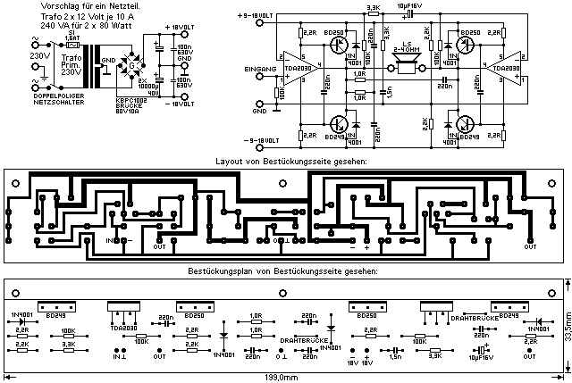
Somewhere on net I read that this is just a working design not a very good amp. pls comment.
And other members pls.... your contribution here, would be valuable for me.
The TDA2030 isn't a bad little chip but in your first post, you stated that you wanted an amp that would output 70-100W into 4 ohms. The TDA2030 is only a 18W max device and even when bridged (which would not be possible with a 4 ohm load), would not provide the output power you require.
A non-bridged TDA729* series chip would provide plenty of power, do it into 4 ohms and, most significantly, work well off a 4A 20V supply. I understand your efficiency concerns, but to keep things simple, you are best simply using a single chip if one is available. Paralleling and bridging an amp, things start to get very complicated and can cause trouble because of the problems with matching the gain and getting the amps to share current properly.
A non-bridged TDA729* series chip would provide plenty of power, do it into 4 ohms and, most significantly, work well off a 4A 20V supply. I understand your efficiency concerns, but to keep things simple, you are best simply using a single chip if one is available. Paralleling and bridging an amp, things start to get very complicated and can cause trouble because of the problems with matching the gain and getting the amps to share current properly.
The output current of an SMPS is usually the peak current. With music being sine waves you only have 4 Apk / sqrt(2) = 2,83 Aeff available. That corresponds to ~32 W into 4 Ohm. Normal SMPS cannot deliver the same amount of overcurrent as conventional unregulated power supplies, so it is pretty likely that you won't get more than 32 W even for transients. Another issue is that not all SMPS are absolutely silent in the audio band.
The TDA729* has the same dimensions as the LM3886. It must therefore be just as limited when it comes to thermal transfer. The trick to get 100 W from it is to use it in class H, what the datasheet calls High Efficiency Application, but then the 6,5 A current limiter threshold may become an issue and the power supply becomes more complex, too.
For 100 W into 4 Ohms a parallel setup is recommendable. According to the Overture Design Guide that requires more or less ±33 V at full load, which means ±40 V or more idle from an unregulated supply. Two ICs in parallel could be easy enough to heatsink. Depending on the woofer and the way it is used a third IC may be necessary. You could google PA150 for a working example, but your SMPS won't do.
The TDA729* has the same dimensions as the LM3886. It must therefore be just as limited when it comes to thermal transfer.
The package to heatsink thermal resistance isn't the determining factor for chipamps with average heatsinking. What determines the thermal limit is the die to case value (called 'theta jc') in the datasheet. For the TDA7294 its 1.5oC/W and for the LM3886 its 1.0oC/W. So the LM wins out over the TDA even though their packaging is identical.
Also Add TDA 2030 to subject line....
Thanks to all for fast reply.
well I will put here again.
Click for the relevent thread
Click for the relevent Circuit diagram.
Blue, Thanks for the valuable information about SMPS.
Yes I understand , all the smps might not be good for audio equipments because of its switching frequency might be in audio range. also its harmonic frequencies might be the problem. for this additional filter is required, and would be taken care of, Pl let me know if any hing else I should take care.
About power delivered by SMPS.
If one supply can deliver ~32W then two can deliver ~74W in BTL mode ( the reason why I am so keen on BTL ).
Yes,.... was about to say....
Thanks to all for fast reply.
Jack I guess you missed the link provided in my previous thread.The TDA2030 isn't a bad little chip but in your first post, you stated that you wanted an amp that would output 70-100W into 4 ohms. The TDA2030 is only a 18W max device and even when bridged (which would not be possible with a 4 ohm load), would not provide the output power you require.
well I will put here again.
Click for the relevent thread
Click for the relevent Circuit diagram.
The output current of an SMPS is usually the peak current. With music being sine waves you only have 4 Apk / sqrt(2) = 2,83 Aeff available. That corresponds to ~32 W into 4 Ohm. Normal SMPS cannot deliver the same amount of overcurrent as conventional unregulated power supplies, so it is pretty likely that you won't get more than 32 W even for transients. Another issue is that not all SMPS are absolutely silent in the audio band.
Blue, Thanks for the valuable information about SMPS.
Yes I understand , all the smps might not be good for audio equipments because of its switching frequency might be in audio range. also its harmonic frequencies might be the problem. for this additional filter is required, and would be taken care of, Pl let me know if any hing else I should take care.
About power delivered by SMPS.
If one supply can deliver ~32W then two can deliver ~74W in BTL mode ( the reason why I am so keen on BTL ).
The package to heatsink thermal resistance isn't the determining factor for chipamps with average heatsinking. What determines the thermal limit is the die to case value (called 'theta jc') in the datasheet. For the TDA7294 its 1.5oC/W and for the LM3886 its 1.0oC/W. So the LM wins out over the TDA even though their packaging is identical.
Yes,.... was about to say....
About power delivered by SMPS.
If one supply can deliver ~32W then two can deliver ~74W in BTL mode
You need two anyway to produce a split supply. BTL would indeed double the power to 64 W with the same pair of SMPS.
At that point you may run into another issue. SMPS usually have an internal connection from the negative output to the case which is at the same time PE and ground. You will have to remove that connection to avoid a short between the negative rail and gnd. That takes some care to make sure that you don't compromise safety. The case must remain connected to PE. With the positive rail connected to ground any internal protective elements may not be working correctly anymore, e. g. fuses that may be in the wrong place after the modification.
100W into 4r0 (a resistor, not a speaker), requires 28.3Vpk and 7.1Apk to be fed simultaneously to the load.
A speaker with easy to moderate reactance will demand at least twice the current that the equivalent resistor will demand.
A severe reactance 4ohm speaker and crossover can demand transients that are 3times what the 4r0 resistor requires.
That puts your PSU and amplifier into target territory of meeting 14Apk to 22Apk.
A 4Apk SMPS cannot get any where near meeting any of those peak demands.
A BA100 when run cold cannot get near those transient demands.
A BPA200 when cold can manage at least 7Apk (that is the guaranteed cold current delivery).
A BPA300, run warm, may just about drive your 4ohm speaker to 100W and meet the transient peak current demand of ~20 to 25Apk.
You will need 6chipamps and six SMPS to get anywhere near your target. That still leaves you with finding the extra 8A to 10Apk between 3*4A and the speaker peak demand.
I suggest you use amplifiers rated to meet your target and forget about trying to use current limited chipamps.
This analysis is way too pessimistic. For a start, the OP is asking for an amplifier into a woofer. This means there is no crossover involved. I've designed a few commercial subwoofer amplifiers (the highest power one being 200W) and not found a woofer to be such an adverse load as you're suggesting here Andrew. But you're right about the SMPSU not being up to the job - its peak current capability can be enhanced with a suitable output capacitor, but its only rated at 80W which is insufficient for the task.
To me, it appears that the limitation will be the power supplies. 2 x 32 W is not going to become 100 W anytime soon. But connected in series (with the appropriate precautions regarding grounding and filtering) they will deliver a steady +/-20 V. According to the AN1192 application note, 20 V happens to be the maximum recommended voltage for a bridged pair LM3886 with a 4 ohm load. The amp will then be able to deliver "about 110W of output power in bridged-mode driving a 4 ohm load", still according to the application note. The chips will current limit at about 11.5 A. Obviously, the SMPS's will run out of current first, so you will not get more than the 64 W continuously.
Still, this setup could actually work reasonably well with decently sized capacitors for filtering and energy storage between the SMPS and the amps. You could easily get peak power well in excess of 100 W. The question will be for how long the capacitor bank can sustain that current draw. Another question will be if you really need 100 W continuously. If the woofer has an efficiency of 85 dB @ 1 W, 100 W is 105 dB. That's pretty loud. Also, most woofers are excursion limited in the deep bass, so a sudden voltage swing from the bridged amp of +/- 35 V or so at 20-30 Hz might be more than enough to damage the woofer.
I'd give it a try. In fact, I have a bunch of LM4780 and Cosel 24V SMPS in the basement waiting for me to find the time to do exactly that.
You need two anyway to produce a split supply. BTL would indeed double the power to 64 W with the same pair of SMPS.
At that point you may run into another issue. SMPS usually have an internal connection from the negative output to the case which is at the same time PE and ground. You will have to remove that connection to avoid a short between the negative rail and gnd. That takes some care to make sure that you don't compromise safety. The case must remain connected to PE. With the positive rail connected to ground any internal protective elements may not be working correctly anymore, e. g. fuses that may be in the wrong place after the modification.
Sorry Blue, For the wrong calculations. It should have been 64W.
About the output negative rail made common with ground of primary side ckt of smps transformer. This is true with some smps. but these days for 2pin smps like that for Laptops, use opto-coupled feedback.This makes it safe for human handling. I have also tried this with the other SMPS of 12 volts available with me. Follow the link for example so it would be easy to understand. Isolated ground.
100W into 4r0 (a resistor, not a speaker), requires 28.3Vpk and 7.1Apk to be fed simultaneously to the load.
A speaker with easy to moderate reactance will demand at least twice the current that the equivalent resistor will demand.
A severe reactance 4ohm speaker and crossover can demand transients that are 3times what the 4r0 resistor requires.
That puts your PSU and amplifier into target territory of meeting 14Apk to 22Apk.
A 4Apk SMPS cannot get any where near meeting any of those peak demands.
A BA100 when run cold cannot get near those transient demands.
You will need 6chipamps and six SMPS to get anywhere near your target. That still leaves you with finding the extra 8A to 10Apk between 3*4A and the speaker peak demand.
I suggest you use amplifiers rated to meet your target and forget about trying to use current limited chipamps.
well this moment concentrating on BA100 mentioned in application note AN1192 as they say you need 20V dual supply for 4E load. But current? and if we are using smps from normal market what should be it rating?
This analysis is way too pessimistic. For a start, the OP is asking for an amplifier into a woofer. This means there is no crossover involved. I've designed a few commercial subwoofer amplifiers (the highest power one being 200W) and not found a woofer to be such an adverse load as you're suggesting here Andrew. But you're right about the SMPSU not being up to the job - its peak current capability can be enhanced with a suitable output capacitor, but its only rated at 80W which is insufficient for the task.
yes, abraxalito, that is a sure concern.I think the difference between 64W and 100W is 1.9db. Still the problem is if I try to draw more current the output might get clipped also would shut smps in protection mode.
To me, it appears that the limitation will be the power supplies. 2 x 32 W is not going to become 100 W anytime soon. But connected in series (with the appropriate precautions regarding grounding and filtering) they will deliver a steady +/-20 V. According to the AN1192 application note, 20 V happens to be the maximum recommended voltage for a bridged pair LM3886 with a 4 ohm load. The amp will then be able to deliver "about 110W of output power in bridged-mode driving a 4 ohm load", still according to the application note. The chips will current limit at about 11.5 A. Obviously, the SMPS's will run out of current first, so you will not get more than the 64 W continuously.
Still, this setup could actually work reasonably well with decently sized capacitors for filtering and energy storage between the SMPS and the amps. You could easily get peak power well in excess of 100 W. The question will be for how long the capacitor bank can sustain that current draw. Another question will be if you really need 100 W continuously. If the woofer has an efficiency of 85 dB @ 1 W, 100 W is 105 dB. That's pretty loud. Also, most woofers are excursion limited in the deep bass, so a sudden voltage swing from the bridged amp of +/- 35 V or so at 20-30 Hz might be more than enough to damage the woofer.
I'd give it a try. In fact, I have a bunch of LM4780 and Cosel 24V SMPS in the basement waiting for me to find the time to do exactly that.
Dear asbjbo, pls try asap 🙂 that would be of big help to me. I have still lot of questions in my mind.
Ok, concentrating on 100W and application note AN-1192, I have list of questions.
1) what is the current required ?
2) What should be the smps current?
3) What size should be rating of heatsink if to be safely worked at 50 deg C ambient temp.
4) The component values given in application note under section 5.2.1 figure are for 8E hope they remain unchanged.
National have provided a table of data that define the heatsink size dependent on Ta, Vpsu, Rload for using their chip at maximum rated temperature.3) What size should be rating of heatsink if to be safely worked at 50 deg C ambient temp.
Unfortunately the chip will repeatedly enter any of it's various protection modes when running this hot.
I always recommend that builders double the heatsink size recommended by National in that table.
If National say 3.8C/W for a single chip, you provide 1.9C/W for a single chip and 0.95C/W for a pair of chips.
Ok, concentrating on 100W and application note AN-1192, I have list of questions.
1) what is the current required ?
2) What should be the smps current?
3) What size should be rating of heatsink if to be safely worked at 50 deg C ambient temp.
4) The component values given in application note under section 5.2.1 figure are for 8E hope they remain unchanged.
I missed a question,
5) what is the phase response of the design. (BA100)? Cause this might matter when its a subwoofer amp.
Can't find BA100 in AN-1192. If you really meant BR100, then that's not suitable here because of the 2R loading on each chip amp (pointed out by jackand08). Given the twin requirements of bridged AND 4R load, it would be most cost effective to use a pair of LM1876s in parallel/bridged, for which you could use the BPA200 schematic in that appnote - you'd get about 80W I think. If you really need 100W, then 4 * TDA2050 or 4 * LM1875 would do it admirably.
- Status
- Not open for further replies.
- Home
- Amplifiers
- Chip Amps
- Lm3886 in BTL mode with 4ohms load and Smps.