Hi,
Attached it is a drawing of my star ground I used in LM3886 built and it is completely silent. You can use it as a template to compare your ground against it. Remember sometime what may worked for somebody it may not worked for you. It depended on how the wire it is laid down etc etc.
Attached it is a drawing of my star ground I used in LM3886 built and it is completely silent. You can use it as a template to compare your ground against it. Remember sometime what may worked for somebody it may not worked for you. It depended on how the wire it is laid down etc etc.
Attachments
Hi,
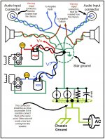
Attached it is a drawing of my star ground I used in LM3886 built and it is completely silent. You can use it as a template to compare your ground against it. Remember sometime what may worked for somebody it may not worked for you. It depended on how the wire it is laid down etc etc.
In my case between the star (connected at chassis) and the mains earth, I have a similar circuit, but with two diodes (1N5408), 10Ohm and 0.1uF.
Roushon.
Tauro,
your diagram is wrong.
The two Zero Volts wires from the smoothing capacitors must NOT be taken to the Main Audio Ground (MAG).
Connect the smoothing capacitor Zero Volts together to form as small a loop area as you can manage.
Bring a single wire/trace from that Zero Volts to the MAG.
your diagram is wrong.
The two Zero Volts wires from the smoothing capacitors must NOT be taken to the Main Audio Ground (MAG).
Connect the smoothing capacitor Zero Volts together to form as small a loop area as you can manage.
Bring a single wire/trace from that Zero Volts to the MAG.
Have you tested this?In my case between the star (connected at chassis) and the mains earth, I have a similar circuit, but with two diodes (1N5408), 10Ohm and 0.1uF........
Your life, or that of your Family, may depend on that diode connection surviving longer than it takes for the Mains Fuse to rupture and for the arc to extinguish.
Have you tested this?
Your life, or that of your Family, may depend on that diode connection surviving longer than it takes for the Mains Fuse to rupture and for the arc to extinguish.
It is installed and running for three years without any trouble! Wandering what you mean.
Edit: So far nothing happened, that does not mean it is correct! I will correct it. Please give little more explanation.
Roushon.
Last edited:
- Status
- Not open for further replies.
- Home
- Amplifiers
- Chip Amps
- LM3886 Hum