Hello all,
I have been following the composite amplifier topic on this forum for a long time and was able to gather many a thing from the experiences of other members. Naturally, I then started trying LM3886 / LME49710 simulations of my own, based on the following starting points that I was able to gather from various threads on this forum.
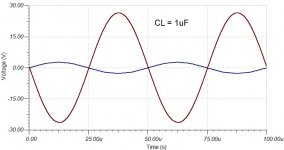
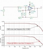
However, lately I happened to find that TINA-TI does not show proper results for the open-loop responses of many parts, possibly due to DC offset saturation. Consequently, my amplifier circuit has not been able to make it to reality, as I am unable to confirm the accuracy of the simulation results (attached).
Though the simulations look good, how accurate are the National / TI models and how far are these from reality? Since this is the first time I'm using TINA (I used PSPICE for over 15 years), I would like to know some of your experiences with this topic.
Looking forward to your comments,
Thanks.
I have been following the composite amplifier topic on this forum for a long time and was able to gather many a thing from the experiences of other members. Naturally, I then started trying LM3886 / LME49710 simulations of my own, based on the following starting points that I was able to gather from various threads on this forum.
- The LM3886 needs to be operated in a closed-loop manner, for "more predictable clipping behaviour", and most of the amplification needs to come from the high performance op-amp and not the power-amp chip.
- Many power-amps are designed for a minimum gain (10 for 3886) and therefore their gains need to be reduced without affecting stability.
- Since LME49710 obtains only a limited voltage swing of 15-16V, the LM3886 needs to be operated at a gain of 2-3V/V, for the typical home / studio amplifier.
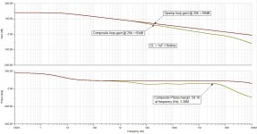
- In order to obtain any significant improvement in performance, the composite audio-band loop-gain needs to be at least 100x (+40dB higher) than that of the power-amp.
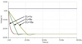
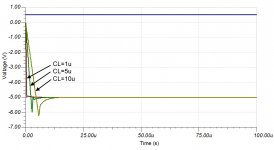
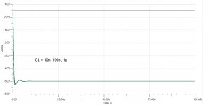
- The composite amplifier needs to remain stable even when presented with a highly capacitive load (e.g. 4.7uF) that emulates the capacitance of typical speaker cables.
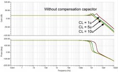
- The capacitor across the inputs of the LM3886 is necessary for large signal stability, clipping recovery and noise/EMI suppression.
- The compensation capacitor should not be a critical circuit component, but only a means to fine-tune the transient performance of the system.
- In order to maintain a high excess loop-gain, the net amplifier gain needs to be minimal, e.g. 10V/V (20dB) for a typical domestic application.
- For a stable composite amplifier, the op-amp cannot be faster than the power-amp.
However, lately I happened to find that TINA-TI does not show proper results for the open-loop responses of many parts, possibly due to DC offset saturation. Consequently, my amplifier circuit has not been able to make it to reality, as I am unable to confirm the accuracy of the simulation results (attached).
Though the simulations look good, how accurate are the National / TI models and how far are these from reality? Since this is the first time I'm using TINA (I used PSPICE for over 15 years), I would like to know some of your experiences with this topic.
Looking forward to your comments,
Thanks.
Attachments

Last edited:
If you require accuracy as opposed to a half educated clue, physically build one.
Simulations are exactly as described ... a simulation that assumes all things are perfect, which in reality, are not.
Simulations are exactly as described ... a simulation that assumes all things are perfect, which in reality, are not.
The composite amplifier needs to remain stable even when presented with a highly capacitive load (e.g. 4.7uF) that emulates the capacitance of typical speaker cables.
I can't imagine any speaker cable coming anywhere near uF territory for self capacitance. Typically it is small capacitive load that cause amplifier stability problems, say 1nF to 100nF give or take.
Electrostatic speakers do present as a more pure capacitive load but would be an unlikely partner to a chip amp.

depending on the implementation there may be no definition of how much amplification comes from each stage (e.g. if only one global feedback loop).Most of the amplification needs to come from the high performance op-amp and not the power-amp chip.
now that has to be a huge speaker cable! speaker wire usually has a capacitance of some tens of pF per meter.(e.g. 4.7uF) that emulates the capacitance of typical speaker cables.
(Mooly was quicker!)
I have been going crazy trying to understand the relationships in the .four and .tran commands. I can make the same amp simulate .00013% THD, or 1.3% THD. There is a relationship with FFT size, frequency, step, and time more complex that I have found a description for. LTSpice is very accurate, if told what to do. I assume the same issues with PSpice. The Bode plots seem to be very good and match reality.
You also need to pay attention to the component models, some are very poor, and to the circuit parasitics. A few nF here and there, layout dependent inductance, cap leakage, even crosstalk effects are all up to you. If I had more trust in the parameters and knew the simulation was 10 times better than real, I would be very happy. I have "magic" parameters I have been using that do in fact bench reliably 10 times worse than the simulation for distortion. So tweaks to my circuits I get reliable differences, but it is working in the dark.
I have been asking for help in this on several forums and have not really made much headway.
Yes, eventually you need to prototype, But that is expensive and you want to be as close as possible first.
I think you are under-estimating how ugly speaker loads can be. Sure, multi-pole output networks reduce performance, but prevent letting the magic smoke out. Fact of life.
I am not sure I totally agree with your comment on how critical the compensation cap is. Sure, it is not the only factor, but that is it's actual primary function. I think maybe a better way to look at is is how far past zero gain do you maintain stability? What are the other poles? Is there a zero sneaking it that is thermal or age related that could mess it up?
Fauxfrench, a member here, did extensive research and measurements on chips with reduced gain. Search for threads that he started. It includes Lm1875,3886,tda7293 and others.
- Many power-amps are designed for a minimum gain (10 for 3886) and therefore their gains need to be reduced without affecting stability.
I can't imagine any speaker cable coming anywhere near uF territory for self capacitance.
depending on the implementation there may be no definition of how much amplification comes from each stage (e.g. if only one global feedback loop).
now that has to be a huge speaker cable! speaker wire usually has a capacitance of some tens of pF per meter.
(Mooly was quicker!)
I use regular electrical wiring (2.5 sq.mm) for speakers and have absolutely no idea what speaker cables measure in terms of capacitance. I remember having read something like that from a thread, have to find out if the context was something different. If my current circuit arrangement is any real, small capacitances below 1uF should not be a problem.
Also, I forgot to mention that the LM3886 is used in the closed-loop manner, as recommended by member tomchris on the following thread, posts # 21-22 and 29. I have added this point to the list above.
https://www.diyaudio.com/community/threads/lm3886-simplest-composite-amp.368884/page-2
I chose to include that point, as the op-amp can usually carry out its duties in a much better way than the power-amp (that has less performance) can.
Fauxfrench, a member here, did extensive research and measurements on chips with reduced gain. Search for threads that he started. It includes Lm1875,3886,tda7293 and others.
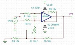
I think you mean that method in which he uses a resistor between the inputs of the LM3886 (here), but I don't use a resistor between the inputs, only the 220pF capacitor recommended by National.
...I can make the same amp simulate .00013% THD, or 1.3% THD. There is a relationship with FFT size, frequency, step, and time more complex that I have found a description for... he Bode plots seem to be very good and match reality.
You also need to pay attention to the component models, some are very poor, and to the circuit parasitics. A few nF here and there, layout dependent inductance, cap leakage, even crosstalk effects are all up to you.
I am not sure I totally agree with your comment on how critical the compensation cap is. Sure, it is not the only factor, but that is it's actual primary function. I think maybe a better way to look at is is how far past zero gain do you maintain stability? What are the other poles? Is there a zero sneaking it that is thermal or age related that could mess it up?
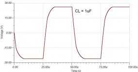
Although I've found the TINA THD function to be totally useless, it somehow manages to obtain the THD of a square wave correctly! The component models are exactly the same as given by TI, for TINA simulator. Of course, I can handle the PCB correctly, as I belong to the (non-audio) industry.
Actually, my circuit is the kind that operates without any external compensation (as you can see from a picture) and its poles / zeroes are a result of the gain-bandwidth products of the constituent devices. The compensation capacitor was added only as a cosmetic adjustment to reduce the effects of the peaking / ringing response.
newvirus2008 said:I don't use a resistor between the inputs, only the 220pF capacitor recommended by National.
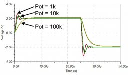
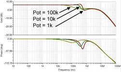
Here's the method that I used for reducing LM3886 gain, without affecting its stability. The idea is to simultaneously use both the inverting and non-inverting gains together to get a net gain that is lower than the minimum recommended value. By adjusting the potentiometer, the shelving bandwidth may also be changed accordingly.
Attachments
Yes, or simply raising the noise gain a shown here in post 19:I think you mean that method in which he uses a resistor between the inputs of the LM3886 (here), but I don't use a resistor between the inputs, only the 220pF capacitor recommended by National.
MT-033
But this is better tested in real than just simulation and as you can see it does work.
Joensd, thanks for the ADI appnote.
However, on second thoughts, I feel that it maybe best to keep the power-amp at its minimum recommended gain. And, if this minimum is also equal to the net closed-loop gain, then the power-amp gain and the feedback factor cancel each other, leaving the op-amp's gain as the excess loop gain available for error correction. This change should not impact stability, as the power-amp's noise gain remains the same as before.
I have also corrected the list in the opening post, and hope it now reads more or less alright.
Right, I was simulating a multiple feedback system with the power-amp in closed-loop configuration.
However, on second thoughts, I feel that it maybe best to keep the power-amp at its minimum recommended gain. And, if this minimum is also equal to the net closed-loop gain, then the power-amp gain and the feedback factor cancel each other, leaving the op-amp's gain as the excess loop gain available for error correction. This change should not impact stability, as the power-amp's noise gain remains the same as before.
I have also corrected the list in the opening post, and hope it now reads more or less alright.
depending on the implementation there may be no definition of how much amplification comes from each stage (e.g. if only one global feedback loop).
Right, I was simulating a multiple feedback system with the power-amp in closed-loop configuration.
So, there's a new simulation based on the revised concept that uses the power-amp gain to cancel the resistive divider, whose results are attached. However, once again, there's the issue of the simulation translating to reality! But I must say that the LM3886 characteristics look very promising.
Attachments

You guys may be interested in this new TI opamp. Power supply voltage max +/-42.5V, and good audio specs.
That will remove the annoying limited output level of audio opams as described in the 1st post.
https://www.ti.com/lit/ds/symlink/o...2Fproduct%2FOPA593%3Fjktype%3Dhomepageproduct
Jan
That will remove the annoying limited output level of audio opams as described in the 1st post.
https://www.ti.com/lit/ds/symlink/o...2Fproduct%2FOPA593%3Fjktype%3Dhomepageproduct
Jan
Interesting device. It always amazes me that there is a need and a market for all these devices to be developed and produced. This one is different though.
TI has several opamps with > +-40V up to +-90V like OPA445, 454, 455, 462 etc.
Would make a nice and compact composite amp like Juma demonstrated here:
Small Class-A with SMPS by Juma
These opamps are on the pricy side though.
Would make a nice and compact composite amp like Juma demonstrated here:
Small Class-A with SMPS by Juma
These opamps are on the pricy side though.
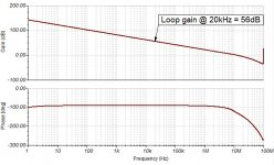
From the TINA macromodel, the OPAx593 loop gain at 20kHz is 56dB, much similar to that of LM3886. However, since this loop gain does not include the resistive divider, it would drop by another 20.8dB for a closed loop gain of 11V/V.
It is due to this issue that I later (since post #10) thought of using the power-amp gain to cancel the divider, leaving the entire op-amp loop-gain available for error correction. For the LME49710, this value would be close to 70dB at 20kHz.
However, I think this opamp can make a very good driver in discrete linear amplifiers. Due to the excellent DC precision, it may also be possible to apply local feedback around the output devices to further stabilise the quiescent current without putting the VBE multiplier on the heatsink.
Attachments
Last edited:
The TINA-TI model for the LM3886 is not great. It works OK for a small signal analysis away from the supply rails. I find the transient model to be reasonably reflective of reality as well. The model does not include THD and also not anything related to the power supply. Not even the supply current (aside from the quiescent current).
I still find the model very useful to eliminate bad circuit candidates. But for deciding between two good circuit candidates you really need to build the circuit.
Tom
I still find the model very useful to eliminate bad circuit candidates. But for deciding between two good circuit candidates you really need to build the circuit.
Tom
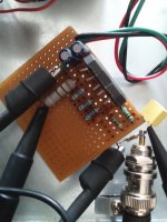
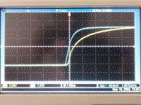
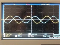
I did build the non-inverting 6dB circuit with some modifications (circuit below). The results for 1kHz square-wave and 3MHz-6MHz sine-wave steps are also attached.
Input = Blue trace (Ch2) and Output = Yellow trace (Ch1), descriptions in the respective filenames.
What I gather from the pictures:
* The circuit is indeed non-inverting with a gain of 2V/V or +6dB as intended, with dynamics suitable for amplifier applications. In fact, a non-inverting 0dB (unity gain) amplifier could also be successfully built, based on the fact that the inverting and non-inverting gains differ exactly by 1. This would also cancel the influence of the resistor divider on the magnitude of the closed-loop gain, which is sometimes a useful thing.
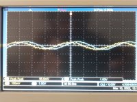
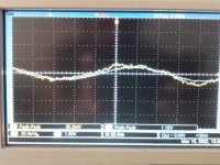
* Though the 6dB circuit works well across the audio band, high frequency results show that it turns a lot of phase, much unlike what the LM3886 TINA macromodel predicts (last picture).
Frequency / Gain / Phase
3M / -8dB / 135*
4M / -14dB / 120*
5M / -20dB / 30*
6M / -34dB / negligible.
Now, it is worth noting that one would get misled if he/she were to look at the audio frequency band alone. So, does it work ? Yes, but not as claimed by the manufacturer's model.
So, what could be wrong with the model when it seems to work for many? Most likely the locations of the non-dominant poles, which are considered important in non-unity-gain-stable (decompensated) opamps.
And, why would the manufacturer model only the dominant pole correctly ? Most likely because that's the way the device was primarily meant to be used and experiments such as this involve undocumented ways of operation that are usually not covered by datasheets / spice models.
Input = Blue trace (Ch2) and Output = Yellow trace (Ch1), descriptions in the respective filenames.
What I gather from the pictures:
* The circuit is indeed non-inverting with a gain of 2V/V or +6dB as intended, with dynamics suitable for amplifier applications. In fact, a non-inverting 0dB (unity gain) amplifier could also be successfully built, based on the fact that the inverting and non-inverting gains differ exactly by 1. This would also cancel the influence of the resistor divider on the magnitude of the closed-loop gain, which is sometimes a useful thing.
* Though the 6dB circuit works well across the audio band, high frequency results show that it turns a lot of phase, much unlike what the LM3886 TINA macromodel predicts (last picture).
Frequency / Gain / Phase
3M / -8dB / 135*
4M / -14dB / 120*
5M / -20dB / 30*
6M / -34dB / negligible.
Now, it is worth noting that one would get misled if he/she were to look at the audio frequency band alone. So, does it work ? Yes, but not as claimed by the manufacturer's model.
So, what could be wrong with the model when it seems to work for many? Most likely the locations of the non-dominant poles, which are considered important in non-unity-gain-stable (decompensated) opamps.
And, why would the manufacturer model only the dominant pole correctly ? Most likely because that's the way the device was primarily meant to be used and experiments such as this involve undocumented ways of operation that are usually not covered by datasheets / spice models.
Attachments


So, maybe I could have made a mistake ? Not likely, as I have checked these things multiple times. However, there's this thing that my power supplies were only about +/- 17V and I don't know if that would make a big difference, but I'd like to know if it would. I'd have to go to the market to get some rectifiers though.
- Home
- Amplifiers
- Chip Amps
- LM3886 Composite amplifier - how accurate are simulated results ?