Hi I have issue with LM3886TF ic configuration. on the output pin 3.3 ohms resistor keeps on burning and don't know the real reason behind this...is any expert share you view on this why resistor keeps on burning??
Attachments
Hard to say without seeing a circuit diagram. If the resistor is part of the 'Zobel Network' which means that resistor would be in series with a small capacitor of around 0.1uF then the usual cause is high frequency oscillation or an unsuitable signal has been applied or the unit has been power up incorrectly (missing grounds etc) which might happen if you are trying to repurpose the board.
Thanks for your reply. here is the clear circuit diagram of the board...is there any issue in IC short circuit or some think else may be issue?Hard to say without seeing a circuit diagram. If the resistor is part of the 'Zobel Network' which means that resistor would be in series with a small capacitor of around 0.1uF then the usual cause is high frequency oscillation or an unsuitable signal has been applied or the unit has been power up incorrectly (missing grounds etc) which might happen if you are trying to repurpose the board.
Attachments
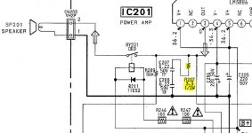
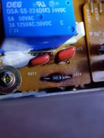
That is the Zobel network. The two series 0.22uF caps in series are equivalent to a 0.11uF.
The resistor has burned because the chip has delivered a high frequency output. The 3.3 ohm at 0.5 watt rating is in my opinion very underrated, however it should survive normal music at normal volume.
The chip may or may not be faulty. All you can do is replace the resistor (it is not very critical, even up to a 10 ohm should work) and see what happens. If the resistor still burns then the chip might be faulty or the chip may be seeing an unwanted high frequency signal applied to its input which it then tries to amplify.
We still do not know how you are using the board. If you are just experimenting and running the board up outside of its normal setting then the problem may be down to how you have it all wired up.
Obviously that does not apply if the resistor failed while the board was correctly installed in whatever equipment it came from.
Hi Mooly,
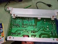
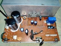
its is subwoofer circuit of sony amplifier which i try to renavate due to this issue i'm unable to use it. i have changed the resistance with 3.3 ohms 1/2 watt with new one but without input the resistance gets keep on burning which i have no clue what is the resolution to fix it...if the chip replacement help out to fix this is issue or not? chip cost around 7$ here before changing it i want to confirm the issue.
its is subwoofer circuit of sony amplifier which i try to renavate due to this issue i'm unable to use it. i have changed the resistance with 3.3 ohms 1/2 watt with new one but without input the resistance gets keep on burning which i have no clue what is the resolution to fix it...if the chip replacement help out to fix this is issue or not? chip cost around 7$ here before changing it i want to confirm the issue.
If you do not have an input connected and the amp is oscillating, you need some more suppression. An RC filter on the input will usually handle it, though I suspect the loopy layout is causing these issues. The signal paths are extremely long with the add-in connections. A more complete schematic will help (from input onwards).
I don't think they designed with open input and unloaded configuration in mind. When you connect a speaker and source, do you get sound?
I don't think they designed with open input and unloaded configuration in mind. When you connect a speaker and source, do you get sound?
When i remove this resistance connect the input with RCA signal, system turned on for a while but when a punch or bass frequency come then speaker protection circuit cut off the output to the speaker using a relay circuit and turn on relay at non punch or bass sequences...If you do not have an input connected and the amp is oscillating, you need some more suppression. An RC filter on the input will usually handle it, though I suspect the loopy layout is causing these issues. The signal paths are extremely long with the add-in connections. A more complete schematic will help (from input onwards).
I don't think they designed with open input and unloaded configuration in mind. When you connect a speaker and source, do you get sound?
this relay trip keeps on happening (clicking noise).
i don't have oscilloscope with me but my friend has one to lab testing..Did you look at the output with an oscilloscope? It's almost certainly oscillating...
is there a way to check these cap's as usually cap burst, bulge or leaks but don't see any symptoms on it..i will try replacing the caps too..Those series capacitors are likely shorted/failed.
Happens all the time.
If you remove the 3.3 ohm you can test those two 0.22uF caps for leakage. They should read open circuit on the highest ohms range on your meter. @wiseoldtech thinks they could be shorted... I'd be really surprised if they were but you should check them.
We can't see the input to the chip in the circuit you posted and so running the chip without whatever normally connects to the input could cause problems. In other words it could rely on the circuitry in front of the chip to maintain a low and defined impedance across the input.
We can't see the input to the chip in the circuit you posted and so running the chip without whatever normally connects to the input could cause problems. In other words it could rely on the circuitry in front of the chip to maintain a low and defined impedance across the input.
Probably oscillation...don't know about the chip but it has robust protection inbuilt. Check supply rails + same as suggested by everyone.
If you remove the 3.3 ohm you can test those two 0.22uF caps for leakage. They should read open circuit on the highest ohms range on your meter. @wiseoldtech thinks they could be shorted... I'd be really surprised if they were but you should check them.
We can't see the input to the chip in the circuit you posted and so running the chip without whatever normally connects to the input could cause problems. In other words it could rely on the circuitry in front of the chip to maintain a low and defined impedance across the input.
I fail to understand why some people think a VISUAL inspection is a way of diagnosing anything.is there a way to check these cap's as usually cap burst, bulge or leaks but don't see any symptoms on it..i will try replacing the caps too..
In order to PROPERLY troubleshoot or diagnose things, test equipment is needed, along with the experience of using said equipment.
The same goes for going to the doctor, right?
He can't tell if an illness or internal issue is going on, without his "tools".
Not everyone can afford an oscilloscope & definitely we need our eyes to diagnose or to see test results from oscilloscope screen. But yes we need tools & experience. I think everyone is in agreement on this.
Most should be able to afford a multimeter, though. That's really all that's needed to check whether those two capacitors have shorted.
I agree with everyone that there are two possible causes: high-frequency output from the LM3886; shorted Zobel capacitors.
If the circuit has worked just fine until now it's unlikely that the LM3886 suddenly went unstable and produced HF output.
If the Zobel capacitors failed the 3.3 Ω resistor would most certainly go up in smoke. While I agree that the 1/8-1/4 W resistor type used here is a bit skimpy I wouldn't just blindly install a resistor of a higher power rating. Same reason as I wouldn't just install a higher ampacity fuse (or rusty nail) if the fuse blew.
Cut the leads on the resistor. It's toast anyway. Then find out (with a multimeter) which of the resistor leads is connected to the Zobel capacitors (hint: it's the one not connected to pin 3 of the LM3886). Measure the resistance from that pin to ground. It should be pretty darn close to infinity. If it isn't, swap the two capacitors in the Zobel network. And actually... If that is the case, I would install a single 100 nF capacitor rated for at least 63 V DC, preferably 100 V DC. Then replace the resistor with a 3.3 Ω (or 2.7 Ω).
The reason the capacitors failed (assuming that's what's going on) could be that they didn't share the voltage across them evenly and one arced over. Putting capacitors in series without ballast resistors is not a good design practice.
Tom
Nice info, didn't know about this.The reason the capacitors failed (assuming that's what's going on) could be that they didn't share the voltage across them evenly and one arced over. Putting capacitors in series without ballast resistors is not a good design practice.
Tom
Caps do short but the odds of two shorting is very unlikely. You should be able to detect HF oscillations with a meter that reads AC and blocks DC Volts when there is no sound. If your meter does not have a DC blocking capacitor then you can add one (~100nF) externally. Causes include bad ground wiring and failed local decoupling and supply capacitors like C205 and C206. A complete schematic might reveal feedback network capacitors that could also cause oscillations, shown as Cc and Cf in the LM3886 data sheet.
But without oscilloscope its hard to find the oscillation source, most of the time i believe. Group loop is another matter.
Techs have both the equipment and the experience.Not everyone can afford an oscilloscope & definitely we need our eyes to diagnose or to see test results from oscilloscope screen. But yes we need tools & experience. I think everyone is in agreement on this.
Trying to "repair" equipment without basic tools and knowledge is futile.
- Home
- Amplifiers
- Chip Amps
- LM3886 burning up 3.3 ohm resistor