Hi,
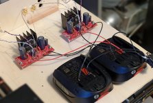
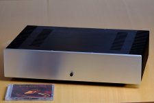
My third GC amp powered by two Li Ion batteries (14,4 v)..
Schematic is the same of :
http://www.diyaudio.com/forums/chip-amps/265827-lm3886-fullrange.html
except R3 change by 825 R
danielwritesbac said that bigger gain change tone and soundstage, that's true, gain with 33/34 give better tone, and a little less soundstage..
But with batterie soundstage is so impressive, and finaly it's not a problem to use high gain..
Phil.
Attachments
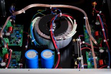
I don't see an output inductor on these boards, so things might simply be unstable at lower gain.
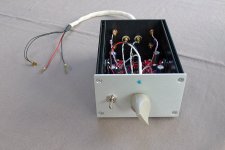
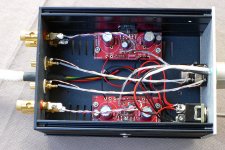
In addition, your wiring has much potential for improvement.
In addition, your wiring has much potential for improvement.
It must be seen as a test and a trial, wiring and casing will come later..
I never use inductor (or resistor//inductor) at output, but my speaker cables are very short.
I never use inductor (or resistor//inductor) at output, but my speaker cables are very short.
Many competent DESIGNERs recommend using an output inductor. Read R.Cordell.
Very few designers are capable of designing an unconditionally stable power amplifier without using an output inductor.
National are the Desingers of your 3876 chipamp.
They include an output inductor in their 3886 datasheet.
Is the 3876 that different?
Very few designers are capable of designing an unconditionally stable power amplifier without using an output inductor.
National are the Desingers of your 3876 chipamp.
They include an output inductor in their 3886 datasheet.
Is the 3876 that different?
Yes, LM3876 is different :
http://www.ti.com/lit/ds/symlink/lm3876.pdf
And at sounding it's better than 3886..
http://www.ti.com/lit/ds/symlink/lm3876.pdf
And at sounding it's better than 3886..
You did not read enough.
Test circuit 1, test circuit 2 and fig3 all show the inductor.
Note (1) for L also describes it's use.
And it is referred to specifically in "Reactive Loading" on p20
Test circuit 1, test circuit 2 and fig3 all show the inductor.
Note (1) for L also describes it's use.
And it is referred to specifically in "Reactive Loading" on p20
Very few designers are capable of designing an unconditionally stable power amplifier without using an output inductor.
Designing an amplifier that unconditionally stable with a resistive load is actually not too bad. Designing an amplifier that's stable with a reactive load (speaker load, basically) and performs well is rather challenging. The Thiele Network (L||R in series with the output) isolates the load from the amplifier at frequencies well beyond the audio band, hence, making it possible to design a high-performance amplifier that is stable even with a reactive load.
National are the Desingers of your 3876 chipamp.
They include an output inductor in their 3886 datasheet.
Is the 3876 that different?
They're different, but not that different. The LM3876 is basically an LM3886 with a smaller output stage and lower output current limit. Not exactly an earth shattering difference there.
Tom
I asked the similar question at Pass forum.
I fully understand the need for output LR network ( I didn't know that it is called Thiele network). But then why Mr. Pass did not recommend it for his F5 (and others) and why many gainclone builders did not either? Are those proven to be stable without LR? I am using $$$ speakers one with F5 and one with 3886 gainclone, so I am worried.
I fully understand the need for output LR network ( I didn't know that it is called Thiele network). But then why Mr. Pass did not recommend it for his F5 (and others) and why many gainclone builders did not either? Are those proven to be stable without LR? I am using $$$ speakers one with F5 and one with 3886 gainclone, so I am worried.
The Pass Labs amplifiers are designed with markedly different parameters to amps like the LM3886 and LM3876. Their sensitivity to the factors that cause oscillations are hence different.
The inductor is a form of insurance, really - which is why often the result of having one is referred to as 'unconditional' stability.
The inductor is a form of insurance, really - which is why often the result of having one is referred to as 'unconditional' stability.
Are those proven to be stable without LR? I am using $$$ speakers one with F5 and one with 3886 gainclone, so I am worried.
No they aren't. Most amplifiers (including the LM3886 and likely the F5) are dominant pole compensated. If you place the pole low enough, the amplifier will always be stable, but it will also have poor performance as you're throwing away loop gain (that's the point of compensation after all). The issue is if the load capacitance becomes the dominant pole. Then the amplifier is suddenly not compensated by its internal compensation capacitor but by the load capacitance. If the pole caused by the load is reasonably close to the pole caused by the internal compensation capacitance, the amplifier will oscillate. That's physics at play and if a designer claims he can design that out, ask if he can suspend gravity as well.
Now, it's possible that some amplifiers are so heavily compensated that any reasonable load capacitance (up to a few uF perhaps) can be driven by the amplifier. If that is the case, I bet the amplifier has rather poor THD in the high end of the audio band as lots of loop gain was sacrificed to make the amplifier stable.
The Thiele network isolates the load from the amplifier, or rather, it inserts a resistor in series with the load. It's much easier for the amplifier to drive a resistor in series with a capacitor than the capacitor (or electrostatic loudspeaker) by itself.
The Pass Labs amplifiers are designed with markedly different parameters to amps like the LM3886 and LM3876. Their sensitivity to the factors that cause oscillations are hence different.
Not really. Any amplifier designed by Nelson Pass, Douglas Self, John Curl, me, or any other will be subject to the laws of physics. An amplifier is a control system. Control system theory, including frequency compensation, applies.
Now, there could be differences in the type of compensation used or in the many design tradeoffs involved in designing an amplifier. Maybe Pass decided he only needed to support up to 10 nF, whereas my design target is a clean transient response at Zload = 8 Ω||100 nF and no oscillations for Cload > 1 uF.
Tom
Last edited:
Hi,
At sounding the Thiele Network change nothing..
In the case of low power (5/10 watts), short speaker cables, no complex impedance speakers (zobel at xover), maybe the Thiele Network is not necessary.
Or, without it's not dramatical 🙂
At sounding the Thiele Network change nothing..
In the case of low power (5/10 watts), short speaker cables, no complex impedance speakers (zobel at xover), maybe the Thiele Network is not necessary.
Or, without it's not dramatical 🙂
Neville Thiele described his Network.I asked the similar question at Pass forum.
I fully understand the need for output LR network ( I didn't know that it is called Thiele network). But then why Mr. Pass did not recommend it for his F5 (and others) and why many gainclone builders did not either? Are those proven to be stable without LR? I am using $$$ speakers one with F5 and one with 3886 gainclone, so I am worried.
It included both the R+C and the L
Both parts make up the Thiele Network.
N.Thiele shows two versions with the R+C preceding the L and the second, less commonly implemented, with the R+C after the L.
Dr E.Cherry published a short paper exmining the Thiele Network and showed that the two versions are at opposite ends of a continuous spectrum of Networks.
I and a few others have posted parts of that paper on this Forum.
I have also posted an excel spreadsheet (for the full spectrum including the two "end condition" Thiele originals) that takes E.Cherry's formulae and gives a range of component values that fit Cherry's conditions.
Libre Office opens the .xls (after deleting the ".txt") but some of the formatting is corrupted, but still legible.
Using MS excel should open the spreadsheet correctly.
Attachments
Last edited:
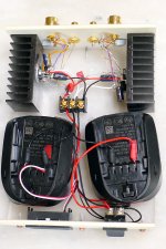
Surprised no one commented on the heat sinks. Those are one quarter the size I'd use to keep an LM1875 cool.
Thank's for asking..
For a LM1875, I use this "ridiculous" heat sink :

In this case, temp is near 26° C (in room 20° C) after one hour of listening..
Before close LM3876, I check the temp, after one hour they give 28° C (in room 20° C), maybe 30° C when box is closed ?
It's low power amp (15 volts max supply), and I need only few watts (speakers are 95 db)..
Phil.
For a LM1875, I use this "ridiculous" heat sink :
In this case, temp is near 26° C (in room 20° C) after one hour of listening..
Before close LM3876, I check the temp, after one hour they give 28° C (in room 20° C), maybe 30° C when box is closed ?
It's low power amp (15 volts max supply), and I need only few watts (speakers are 95 db)..
Phil.
Attachments
For those interested in the heat sink math and the various tradeoffs surrounding thermal design, have a look at my Taming the LM3886 - Thermal Design page.
With 95 dB speakers, you're probably running a few mW (do the math!). This means the chip amp is basically running at idle dissipation. With a ±15 V supply, that's about 1.5 W. That's why the amp does not get more than lukewarm even after hours of operation.
Now, if you loaded the amp with a 4 Ω resistor, swapped the batteries for a lab supply to prevent droop, and ran the amp at peak power dissipation with a sine wave, it would get rather hot and possibly overheat. Thankfully, most people don't do that.
I ran one channel of my 4xMOD86 amp (LM3886-based, shown in attachment) at peak power dissipation (~40 W dissipated) for about an hour using a sine wave signal. The heat sink reached 40 ºC. With two channels running, the heat sink would have reached 60 ºC, which is about as high as I'd ever want an external heat sink to be. The heat sinks measure about 300x90x50 mm. The base of them is 10 mm thick.
Math. Physics. They actually do work... 🙂
Tom
Attachments
Last edited:
Thank's Tom for that clarification 🙂
Always, I have this problem with LM amp..
My dac give about 2,1 volts, and I have to install a pre attenuator before pot.
Here it's 15 db (gain 33 for this amp), without pre att the sound is as "damaged".
With LM3886 (gain 28) I use 10 db.
I think that the best input is around 1,5 volts ?
Always, I have this problem with LM amp..
My dac give about 2,1 volts, and I have to install a pre attenuator before pot.
Here it's 15 db (gain 33 for this amp), without pre att the sound is as "damaged".
With LM3886 (gain 28) I use 10 db.
I think that the best input is around 1,5 volts ?
I don't understand your question.
I'd configure the LM3886 for a gain of 10x (20 dB) as that provides the lowest THD. Add gain further up the chain (in the preamp) if needed.
With ±15 V rails, the LM3886 can probably deliver about 12-13 V peak swing. So max Vin = 13/(10*sqrt(2)) = 919 mV RMS. Perfect for modern sources, such as phones, tablets, computers, USB powered DACs, etc.
Tom
- Status
- Not open for further replies.
- Home
- Amplifiers
- Chip Amps
- LM3876 powered by Li Ion