Thanks a lot for your explanations... I (hope) will try the circuit with 2 LM1875+MJ15003/15004 and +/-40v PSU... I think for 200W/4R its a simple design..
u're suppossed to use a single rail supply I.E +40V only i nthat circuit..the ground is provided by the divider to the right consisting of the 2k2 resistors...
So we will use a single 40v or symmetrical 40v for LM1875? (sorry my poor English but I didnt understand your post!)
I tried that exact same combination a while back. Worked ok but I didn't pursue it.JojoD818 said:I saw a sub amp using an LM3875 with TIP35C/TIP36C as outputs. Has anyone tried this?
http://www.diyaudio.com/forums/showthread.php?s=&threadid=15742&highlight=
>I tried that exact same combination a while back. Worked ok but I didn't pursue it.
http://www.diyaudio.com/forums/show...5742&highlight=
Here we discuss a better way to improve the chipamps.
The first circuit shows exact another way.
Compare it with Tietz/Schenk
http://www.diyaudio.com/forums/show...5742&highlight=
Here we discuss a better way to improve the chipamps.
The first circuit shows exact another way.
Compare it with Tietz/Schenk
Circlotron,
Hi! The link you provided is not working. But if you are talking about your "gc afterburner", then I also saw that implementation too. Can you please describe the behaviour of that circuit, I mean, does the output transistors really kick in at a 0.6V voltage drop at the 1 ohm resistor?
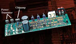
I saw an almost US$1000 subwoofer made by a well known company that uses this type of amp, 1 chipamp, and a pair of complimentary output transistors. 😀 Now that powered sub really sells here in my country for hi-end HT. 🙂
Please inject some more thought in this circuit.
Best regards,
JojoD
Hi! The link you provided is not working. But if you are talking about your "gc afterburner", then I also saw that implementation too. Can you please describe the behaviour of that circuit, I mean, does the output transistors really kick in at a 0.6V voltage drop at the 1 ohm resistor?
I saw an almost US$1000 subwoofer made by a well known company that uses this type of amp, 1 chipamp, and a pair of complimentary output transistors. 😀 Now that powered sub really sells here in my country for hi-end HT. 🙂
Please inject some more thought in this circuit.
Best regards,
JojoD
Hi JojoD. The link works ok now.  Yeah, it was the gainclone afterburner thingo. The operation was covered pretty much in detail in that thread so there's not a lot I can add. Maybe if you ask specific questions.
The output transistor does indeed come to the rescue of the amp chip when it's load current tries to exceed approximately 0.6 amps in this case. (0.6 volts across 1 ohm). The important thing to note is that the LM3875 output current =levels off= at 0.6 amps and it is the *excess* that is handled by the big transistors.
Also, there is no risk of crossover distortion like there would be if the 1 ohm resistor was not there. Also also, you don't have to fiddle with biasing the transistors or with temperature compensating the bias current. There is so little there that almost nothing could go wrong. It certainly fits in with the minimalast gainclone philosophy. An ideal "next step" I reckon.
Yeah, it was the gainclone afterburner thingo. The operation was covered pretty much in detail in that thread so there's not a lot I can add. Maybe if you ask specific questions. The output transistor does indeed come to the rescue of the amp chip when it's load current tries to exceed approximately 0.6 amps in this case. (0.6 volts across 1 ohm). The important thing to note is that the LM3875 output current =levels off= at 0.6 amps and it is the *excess* that is handled by the big transistors.
Also, there is no risk of crossover distortion like there would be if the 1 ohm resistor was not there. Also also, you don't have to fiddle with biasing the transistors or with temperature compensating the bias current. There is so little there that almost nothing could go wrong. It certainly fits in with the minimalast gainclone philosophy. An ideal "next step" I reckon.
Hi Circlotron, I am really intrigued by the operational character of your afterburner. With your permission, I would like to try my hands on your circuit soon. I plan to install the chipamp and the power transistor on a single heatsink to utilize the chipamp's thermal protection scheme.
BTW, the picture is the amp of an active (powered) sub that I saw personally.
Regards,
JojoD
BTW, the picture is the amp of an active (powered) sub that I saw personally.
Regards,
JojoD
Attachments
Driving the booster transistors from the power supply pins is very similar to the gainclone afterburner thingo.
The IC drives the load directly until the 0.65V threshold of the outputs are reached, this part is basically the same.
What is different is output efficency.
At full output the gainclone afterburner thingo wll only get within 4V~5V or so of the power supply rail.
Driving from the power supply pins gives you rail-to-rail output, less the saturation drop of the booster transistors used (usually less than 1V).
One built with 2N3055/2955 powered on ±28V got within 0.3V of the rail with 7A peak collector current.
30% more power was available, although that is only 1.2dB more, but it ran much cooler too. I considered this a big plus, but the powers that be just decided to make the heatsink smaller and pocket the savings.
Wow!djk said:One built with 2N3055/2955 powered on ±28V got within 0.3V of the rail with 7A peak collector current.

With the transistors driven from the power supply pins the IC output transistors and the external transistors together become a pair of complementary feedback pairs. Some people say CFP's can be inclined to oscillate on peaks but I think the benefits are well worth the risk.
Maybe you could make a combination of both types...?
- Status
- Not open for further replies.
- Home
- Amplifiers
- Chip Amps
- Lm3875 + Tip35c/tip36c