Paku,
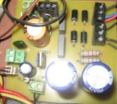
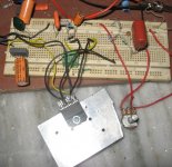
With the proto-boards, it's really tough to get a good result...the lead length and the capacitive parasitics typically cloud all the issues completely.
Of course, you might complain that the "house ground" seemed to quiet things down, but it's hard to predict much of anything given the prototyping method shown in the picture.
Dan
yea, you are right...
But can you please suggest my next steps...because this frustrating me a lot..
thank u guys for your active supports....Long live DIY community...
But can you please suggest my next steps...because this frustrating me a lot..
thank u guys for your active supports....Long live DIY community...
Paku,
Most likely source of noise pickup is the input wiring. You say it's noisier with the input disconnected. Yes...it certainly will be owing to the relatively high input impedance and pickup on the non-shielded leads.
You could help your noise a lot if you used shielded cable for the input circuit instead of the loose wires. Sitting the whole deal inside a metal (steel) box would help also. Also, keep the feedback components short.
I might also try to solder the bypass caps (at least the small value ones) right on the chip leads. Perhaps the same idea for the 1K and 22K gain setting resistors.
I don't think you have schematic problems at this point, just all your long loose wires are picking up hum.
Dan
Akitika GT-101
- Status
- Not open for further replies.
- Home
- Amplifiers
- Chip Amps
- lm3875 noise problem--suggestion required