Sure the line voltage will fluctuate but why incur an additional loss on top of that (plus the extra part)? Losing about 3 volts across the rails isn't that significant to the ear, but the amp takes a hit in output power. For example, a 50 watt amp becomes 45 watts if it loses just one volt rms of output swing.
I agree. Using two bridges, unnecessarily increases the power dissipation. In my measurement are lost needlessly 4 watts on 270w. Enclose the measurements for comparison using the same loads in 2 circuits with one bridge and two bridges.
regards, luigi
Nonsense! Just how is the single full wave bridge not utilizing the transformer to the fullest if the two secondaries are joined in the middle to make it like the center tap? Current flows in both secondaries on both half cycles. Current would be the same but with two extra diodes per half cycle with two FWB.
The ground layout is completely different. There are no direct connections between the transformer(s) and the amp ground.
Here is a layout with all the extra diodes.
Attachments

Hello,
Tried building a differential input LM3875 amp using the ChipAmp boards. Want to drive it directly from differential outputs from a DSP crossover's DAC's.
Build up the LM3875 ChipAmp boards as described which are the same as used here to try. Used 2-1K Ohm series resistors for each input with the 20K feedback resistor and 20K Ohm resistor to ground on the + input to give a gain of 20.
The amps with just the Zobel network on the output oscillate at ~300KHz with a non-sinusoidal waveform. Both amp channels do it. I added 10000uF/50V caps to each power supply leg at the bridge board to help lower 60Hz noise. The amp boards still have the two 1500uF PS caps installed to keep the leads short for stability.
Has anyone else run into this issue with these amps?
I have not tried modifying the circuit with the other components shown in this build for stability increase, just the standard build with the added resistors for balanced inputs.
I think you have described a differential input.
But it is not a balanced impedance connection.
But that does not affect your oscillation.
But it is not a balanced impedance connection.
But that does not affect your oscillation.
Yes, it is a balanced input connection, not output.
The circuit diagrams from NS looks like it will support it since both Inverting and Non-Inverting designs are possible.
The circuit diagrams from NS looks like it will support it since both Inverting and Non-Inverting designs are possible.
Hal,
post43 shows an arrangement that matches your description.
That is a differential input. The amp reads the difference between the Hot and the Cold and processes (amplifies) that difference
But post43 is not a balanced impedance connection.
post43 shows an arrangement that matches your description.
That is a differential input. The amp reads the difference between the Hot and the Cold and processes (amplifies) that difference
But post43 is not a balanced impedance connection.
Yes, that is the balanced amplifier configuration that I am using, except it is balanced impedance input. The ground connection has been moved to use both inputs.
The input resistors are both 1K Ohm and the feedback and ground resistors are 20K Ohm for a gain of 20.
Will check everything again.
The input resistors are both 1K Ohm and the feedback and ground resistors are 20K Ohm for a gain of 20.
Will check everything again.
I checked all the component placement and values and using post #43 as a parts guide, the circuit is correct. The zobel networks are installed as well.
The two film bypass caps across the 1500uF electrolytics in the schematic are not in the kit or on the pc board silk screen, even though there are two solder pads per cap that would work if mounted underneath the pc board.
Will have to try the extra components for stability in the setup.
The two film bypass caps across the 1500uF electrolytics in the schematic are not in the kit or on the pc board silk screen, even though there are two solder pads per cap that would work if mounted underneath the pc board.
Will have to try the extra components for stability in the setup.
post43 is not balanced.
The decoupling common connection is effectively at ground.
This is linked to the Cold Input.
This destroys the balanced impedance.
The decoupling common connection is effectively at ground.
This is linked to the Cold Input.
This destroys the balanced impedance.
For the circuit I am using, the ground at the junction of R2 and R3 from the schematic in post #43 is removed and R2 and R3 connection separated. R2 is grounded as in the schematic, and the inputs are via R1, +In and R3, -In via 1K Ohm resistors. R2 and Rfb are both the 22K Ohm resistors from the kit. The amp gain should be 22, not 20 as I posted before.
That gives a balanced signal input connection referenced to ground to the differential input circuit.
Not sure what the balanced impedance reference means in this case. The resistance on both inputs should be 23K Ohms.
That gives a balanced signal input connection referenced to ground to the differential input circuit.
Not sure what the balanced impedance reference means in this case. The resistance on both inputs should be 23K Ohms.
If your sch is different from post43, then show it.
Without your sch, I cannot see how you can get a balanced impedance input converting to an unbalanced output with just a differential (input) power opamp.
Without your sch, I cannot see how you can get a balanced impedance input converting to an unbalanced output with just a differential (input) power opamp.

Via the same ground setup as in schematic in #43 for both input and output ground in a +22VDC/-22VDC supply.
If your input is voltage referenced to the output, then the circuit is not balanced.
The output does need a reference, otherwise it could end up anywhere between the supply rails.
The output does need a reference, otherwise it could end up anywhere between the supply rails.
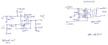
Here is the full schematic.
It is a fully balanced input differential amp, with the balanced input polarities marked.
Power supply is a dual bridge rectifier dual secondary winding dual supply for +/-22VDC input.
Very similar to any opamp circuit for going differential input to singled ended output load. Just a power opamp from the LM3875 schematic.
Attachments
Here is the full schematic.
It is a fully balanced input differential amp, with the balanced input polarities marked.
Power supply is a dual bridge rectifier dual secondary winding dual supply for +/-22VDC input.
Very similar to any opamp circuit for going differential input to singled ended output load. Just a power opamp from the LM3875 schematic.
Hi,
Did you manage to get this circuit working without the oscillation? I'm also going to experiment with differential inputs but maybe throw in a 600:600 ohm input tx.
cheers.
- Status
- Not open for further replies.
- Home
- Amplifiers
- Chip Amps
- LM3875 Chipamp