Hello,
I'm retrofitting a pair of LM3875's into a 1970's Realistic STA-77 amp. The amplifier power supply uses a center tapped power supply at 60v. Is this too much for the IC? I have been told that this is too much, but the datasheet states that it can take 85 volts.
The power reads
60------0------60
|-------|
30v
If it's too high, could I just use the center tap to half the voltage?
Thanks,
You mention a 60V power supply. How is this measured? I can think of 4 possibilities, only one of which would work well.
A few more details would make it easier to identify what you are trying to do, so that your question can be accurately answered.
To summarize, the LM3875 is really designed for a dual-rail DC power supply. The power supply rails should be equal but opposite voltages, with the TOTAL voltage between them being between 20V DC (slightly pointless) and 84V DC (pushing things WAY too hard). Really, you should read the datasheet at http://www.national.com/ds/LM/LM3875.pdfand determine your supply voltage based upon your desired output wattage and your speaker impedance.
Good luck!
- The power supply has dual DC rails, one +30V DC and one -30V DC, giving 60V DC between the rails. This setup would work well for an LM3875.
- The power supply has dual DC rails, one +60V DC and one -60V DC, giving 120V DC between the rails. This setup would be completely unworkable for an LM3875, which is designed for an absolute maximum supply of +/- 42V DC.
- The power supply transformer has a 60V AC center tapped secondary. This means that measured from the center tap to either end of the winding is 30V AC. From one end of the winding to the other would be 60V AC. This setup is really not a good idea with an LM3875, as it would give about +/- 42V DC once rectified. This is the absolute maximum for the LM3875; any increase due to transformer regulation would cause the chip to shut down, or even fry something.
- The power supply transformer has a 120V AC center tapped secondary. This means that measured from the center tap to either end of the winding is 60V AC. From one end of the winding to the other would be 120V AC. Run, don't walk away from this one. That setup might work well for a tube amplifier, but is totally inappropriate for any solid state amp of reasonable wattage.
A few more details would make it easier to identify what you are trying to do, so that your question can be accurately answered.
To summarize, the LM3875 is really designed for a dual-rail DC power supply. The power supply rails should be equal but opposite voltages, with the TOTAL voltage between them being between 20V DC (slightly pointless) and 84V DC (pushing things WAY too hard). Really, you should read the datasheet at http://www.national.com/ds/LM/LM3875.pdfand determine your supply voltage based upon your desired output wattage and your speaker impedance.
Good luck!
The STA-77 is rated 16 watts per channel into 8 Ohms. So the output from the DC side of the supply is probably more like 30-0-30 with light or no load. If the original power amp section is still working, I wouldn't bother changing it out for IC's. The ICs might get you slightly more output power that is not really noticeable. If the original amp is not functioning, I'd be more inclined to repair it.
You mention a 60V power supply. How is this measured? I can think of 4 possibilities, only one of which would work well.
- The power supply transformer has a 60V AC center tapped secondary. This means that measured from the center tap to either end of the winding is 30V AC. From one end of the winding to the other would be 60V AC. This setup is really not a good idea with an LM3875, as it would give about +/- 42V DC once rectified. This is the absolute maximum for the LM3875; any increase due to transformer regulation would cause the chip to shut down, or even fry something.
I think that this is how it is. Only, it measures 60volts between the two hot contacts and 30volts between the hot and middle.
The final end was burned out, that is why I'm attempting to repair it using the chipamp. The original amp used the 2SD313 Transistor, the datasheet can be found here:
http://www.datasheetcatalog.org/datasheet/WINGS/2SD313.pdf
It states 60 volts as well, so I think that this is giving out 60 volts...
I went ahead and hooked it up, it ran for awhile and the chips didn't seem to get too hot, except one channel was around 10X louder than the other.
The LM3875 can operate up to 94V + to - ie + 47V, However, it is recommended to keep the rails a bit lower than that at + 35V.
The LM3875 can operate up to 94V + to - ie + 47V, However, it is recommended to keep the rails a bit lower than that at + 35V.
According to the datasheet, the absolute maximum voltage is 94V (+/-47) non-operating and 84V (+/- 42) operating.
Hi Katie or her Dad,
just in case my memory is playing tricks with me, I downloaded a new copy of the 3875 datasheet direct from National.
I have had a read through reminding me of many features that National draw our attention to. I cannot find the reference to
Could you highlight which paragraph and/or which diagram you are referring to that imparts this information?
just in case my memory is playing tricks with me, I downloaded a new copy of the 3875 datasheet direct from National.
I have had a read through reminding me of many features that National draw our attention to. I cannot find the reference to
if the supply voltage is outside +-35Vdc.runs into protection mode too easily.
Could you highlight which paragraph and/or which diagram you are referring to that imparts this information?
New NS Datasheet page 10...
Depending of the driver...
I find this diagram very important as it explains how you have to chose your supply voltage according to your driver.
Or, in the case of nige838, how to adapt the driver : insert a resistor at the output of the amp (~2 ohm or more) if your driver lowest impedance is less than 8 ohms... but 42V seems really out of range 🙁
Attachments
Last edited:
Yes Leglandu,
That diagram is very informative and useful.
But first a gripe with National.
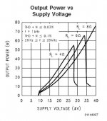
They state on the diagram 4 ohms (Greek symbol omega).
But they actually mean 4r0 pure resistance as the dummy load. similarly for 6r0 and 8r0.
They do not imply by the use of "ohms" that these are test results for driving reactive speakers.
Let's look at the RLoad=4r0 plot.
It shows a maximum of 55W into 4r0 @ <=0.03% distortion+noise and that this is available when +-33.5Vdc is at the Power Input pins.
55W1 into 4r0 is equivalent to 21Vpk & 5.24Apk at the output PIN.
We can see from other diagrams and data that the 25degC 10ms pulse typical output limit is 6Apk and that the clipping voltage is ~4.5V for 8r0 at +-35Vdc supply
The clipping voltage for 4r0 is bound to be much higher than ~4.5V due to the doubled current being delivered. I wonder why they don't show 4r0 clipping voltage as they do for the 3886?
the difference between +-33.5Vdc supply PIN voltage and 21Vpk output voltage @ 5.24Apk is 12.5V. That cannot be the 4r0 clipping voltage. which at worst would be <=~9V
This diagram is showing a protected limit even though it states 0.03% D+N and that is confirmed by the continued low output current still available at even higher supply PIN voltages. The output has been limited at well below maximum output for a 0.03% D+N limit.
You can do similar for 6r0 Rload.
You can do even more by examining the 8r0 performance for which extra data is provided. (75.5W into 8r0 and the equivalent 34.7Vpk @ 4.34Apk when +-40Vdc is at the Power PINs and 0.03% D+N, 5.5V clipping limit @ +-40Vdc)
That diagram is very informative and useful.
But first a gripe with National.
They state on the diagram 4 ohms (Greek symbol omega).
But they actually mean 4r0 pure resistance as the dummy load. similarly for 6r0 and 8r0.
They do not imply by the use of "ohms" that these are test results for driving reactive speakers.
Let's look at the RLoad=4r0 plot.
It shows a maximum of 55W into 4r0 @ <=0.03% distortion+noise and that this is available when +-33.5Vdc is at the Power Input pins.
55W1 into 4r0 is equivalent to 21Vpk & 5.24Apk at the output PIN.
We can see from other diagrams and data that the 25degC 10ms pulse typical output limit is 6Apk and that the clipping voltage is ~4.5V for 8r0 at +-35Vdc supply
The clipping voltage for 4r0 is bound to be much higher than ~4.5V due to the doubled current being delivered. I wonder why they don't show 4r0 clipping voltage as they do for the 3886?
the difference between +-33.5Vdc supply PIN voltage and 21Vpk output voltage @ 5.24Apk is 12.5V. That cannot be the 4r0 clipping voltage. which at worst would be <=~9V
This diagram is showing a protected limit even though it states 0.03% D+N and that is confirmed by the continued low output current still available at even higher supply PIN voltages. The output has been limited at well below maximum output for a 0.03% D+N limit.
You can do similar for 6r0 Rload.
You can do even more by examining the 8r0 performance for which extra data is provided. (75.5W into 8r0 and the equivalent 34.7Vpk @ 4.34Apk when +-40Vdc is at the Power PINs and 0.03% D+N, 5.5V clipping limit @ +-40Vdc)
Last edited:
???
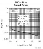
Now, I feel confused about their diagram : how can this chip provide up to 66W in 6 ohms and ~77W at 8 Ohms for 0.03% THD+N ?
I thought it was about the max power available before clipping with the falling curves to show when the max power of the amp collapsed and that's all 😱
But perhaps I was not so wrong as clipping seems to arrive brutally, per their "THD+N vs Output Power" diagram below ?
Sorry but concerning the 4 Ohms load, I see 55W when +- is 28Vdc, not 33.5... if you are still referring to the above diagram, so not sure to perfectly understand all of your demonstration.... It shows a maximum of 55W into 4r0 @ <=0.03% distortion+noise and that this is available when +-33.5Vdc is at the Power Input pins. ...
Now, I feel confused about their diagram : how can this chip provide up to 66W in 6 ohms and ~77W at 8 Ohms for 0.03% THD+N ?
I thought it was about the max power available before clipping with the falling curves to show when the max power of the amp collapsed and that's all 😱
But perhaps I was not so wrong as clipping seems to arrive brutally, per their "THD+N vs Output Power" diagram below ?
Attachments
Oups, seems that I repeat what you already explained AndrewT, sorry, my English is poor so I often have understanding problems... 🙁
my oops !!
I have gone back and looked and see I picked out the voltage for the 6r0 load and the power for the 4r0 load.
You are correct to not simply believe everything I type.
It is always worth reading, thinking, deciding which if any parts to read as believable and which are nonsense and which, if any, are fact.
This project needs a voltage regulator board added. Decibel Dungeon has some examples. Building a Gainclone chip amp with a regulated power supply (PSU). Pedja Rogic Audio Pages - Chip Based Power Amp i.e. Gainclone - Regulated Supplies
Probably some contact problems left in the preamp section. Clean all switches and pots in the signal path with mild contact cleaner that possibly has a sealing function (vaseline spray will do for the latter if need be). I guess you have checked your feedback resistors?I went ahead and hooked it up, it ran for awhile and the chips didn't seem to get too hot, except one channel was around 10X louder than the other.
BTW, I'd look into swapping the main filter caps. Those are likely to be rather small in a 16 watter, and they're like 30 years old and not likely to be premium quality anyway. (I hope you have already replaced remaining "small potatoes" 'lytics with good-quality new ones.) I'd look for mechanically-fitting 6800µ to 8200µ, 35V or 50 V jobs.
I'd look for mechanically-fitting 6800µ to 8200µ, 35V or 50 V jobs.
I wouldn't look for the 35v for a 30v rail because they won't last a long time.
Use the 50v or 63v caps.
- Status
- Not open for further replies.
- Home
- Amplifiers
- Chip Amps
- LM3875 at 60 volts?