Sorry if this is a remedial question - but does anyone know or can recommend a simple circuit for controlling the LM3866 mute circuit using a microcontroller with a 3.3V output voltage. If the mute was controlled with a positive voltage, I wouldn't have an issue, but I'm unsure how to control the negative voltage using a positive high signal from the microcontroller. It seems like it needs to sink more than 0.5ma of current to disable the mute.
If anyone has any suggestions, please let me know. thanks.
If anyone has any suggestions, please let me know. thanks.
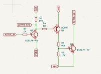
I haven't tested it yet, but between a few comments here and on Reddit, I pieced together a little schematic using two NPN and one PNP transistor. In the simulations it seems to work. Basically it switches on the negative rail using a 3.3V positive signal. I'll feed that rail to the mute pin.
NEG is the unswitched negative rail (-30V), ACTIVE_OUT is the switched negative rail that goes between almost no current and full current when ACTIVE_IN is high.
NEG is the unswitched negative rail (-30V), ACTIVE_OUT is the switched negative rail that goes between almost no current and full current when ACTIVE_IN is high.
Attachments
Your schematic should work fine, but can be simplified if you wish.
I’m responding on an IPad, so will describe in text description. Discard Q2, ground base of Q1, ACTIVE_IN drives emitter of Q1 through a 10k resistor. When active, Q1 forms a 0.27mA current source, i.e. (3.3-0.6)V/10k. R5 can be replaced with a wire; dissipation in Q1 will be about 0.27mA * NEG. Eg. 0.27mA * 30V = 9mW.
I’m responding on an IPad, so will describe in text description. Discard Q2, ground base of Q1, ACTIVE_IN drives emitter of Q1 through a 10k resistor. When active, Q1 forms a 0.27mA current source, i.e. (3.3-0.6)V/10k. R5 can be replaced with a wire; dissipation in Q1 will be about 0.27mA * NEG. Eg. 0.27mA * 30V = 9mW.
Last edited:

I'm doing exactly that - HCPL-817 is the device I'm using. You still need the current-setting resistor
Yah I left the resistor and cap combo (so it has a slow ramp up and down), and am just switching the negative voltage. Thanks.
Hey BrianL, can you explain how you hooked it up a bit more? I haven't used an optocoupler before. I'm assuming the left hand side is just the 3.3V with a current limiting resistor? How did you hook up 3 and 4? I'm guessing the negative rail goes on the emitter and the switched part is the collector? Is that right?
Attachments
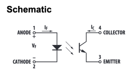
I'd put the emitter to the MUTE pin and collector to ground. That'll pull the MUTE pin close to ground, thereby causing all the current to flow in the optocoupler and none of it in the MUTE pin.
Tom
Tom
Hey Tom, thanks for chiming in.
Just want to make sure I understand, since I wanted to use a high 3.3V signal to unmute it (or when it's low, to be muted). Is your configuring doing that? It sounds like that would mute it, but doesn't it need the negative rail voltage somehow too to unmute it? Are you saying the negative rail is still connected as normal (via a resistor), and this optocoupler is just connected to the pin directly?
Just want to make sure I understand, since I wanted to use a high 3.3V signal to unmute it (or when it's low, to be muted). Is your configuring doing that? It sounds like that would mute it, but doesn't it need the negative rail voltage somehow too to unmute it? Are you saying the negative rail is still connected as normal (via a resistor), and this optocoupler is just connected to the pin directly?
Connect Cmute and Rmute as always. Then connect the optocoupler as I described. Turn the LED on in the optocoupler to mute the LM3886. If you want the opposite, invert the signal (or just flip the bit in the software).
Tom
Tom
- Home
- Amplifiers
- Chip Amps
- LM3866 mute circuit - control with microcontroller