hey guys
i built myself an amplifier for a speaker (4ohms, 5 watts) using LM386, according to the schematic in the datasheet (attached to post), with gain 20.the problem is that as soon as i turn it on, it oscillates.when the input pot is at the lowest level, i can just hear the music playing on the speaker (using ipod for signal into amplifier).it oscillates all the way to max volume through pot on the amplifier.also, inplace of the 0.05microfarad cap, i used a .1microfarad cap as it wasnt available.rest of the circuit is same.
i even changed the gain to 200, connecting a cap between pin 1 and 8, and then adding a bypass cap between pin 7 and ground, intrestingly, the pot, when moved by a very small amount, doesnt produce oscillations now.above the certain value, again oscillations.
i think its a problem of grounding.as in the gain 20 mode, it stops oscillation when i touch come of the wires, but once i move the pot's control, oscillation starts again.
please help guys.
Attachments
Hi
It could be a layout/wiring problem. Ideally the loudspeaker wires should be twisted together, the power supply wires should be twisted together, the input signal should use screened cable, and the loudspeaker wires should be kept away from the input signal wiring.
It might also help to have a capacitor between pins 4 and 6 close to the chip, to decouple the supply rail to ground.
btw: Using 0.1uF instead of 0.05uF is fine.
I assume it's RF oscillation, or is it audible?
What sort of power supply are you using, and how is it built - PCB or point-to point wiring or...?
Cheers - Godfrey
The chip's got one built-in (50K) - it's pretty stupid-proof re biasing.Could be wiper lift. I would try a high value resistor from pin 3 to ground.
Do you have a power supply decoupling cap between V+ and GND? You need one, but it isn't shown in the schematic.
Thanx everyone for the replies.also, i'd try the twisted wire thng.the amp is picking up noise frm my cellphone.also,in my circuit,i had a particular place for grounding connections (its a conducting strip on the board), but the connections are at the opposite ends.can it create problems?also, do capacitor and resistor legs protruding out need to b chipped off?and wht shud be the reading of the decoupling cap between V+ & ground?electrolytic or ceramic?also, please indicate al the places in the circut where these caps are necessary.
Hey Godfrey,
its not a PCB.and the power supply is 9VDC Battery. Also, what should be the value of cap between pin 6 and 4?my layout isnt very planned and clean is a fact tht is very true.thanx.
Hey Godfrey,
its not a PCB.and the power supply is 9VDC Battery. Also, what should be the value of cap between pin 6 and 4?my layout isnt very planned and clean is a fact tht is very true.thanx.
Last edited:
hi everyone
putting a 0.1 microfarad cap between the V+ and ground worked a charm.but then there's a lot of distortion.maybe my speaker is not able to take the gain well (4ohms 5 watt).what say guys?am i right? my amp gain is 20.
thanx
putting a 0.1 microfarad cap between the V+ and ground worked a charm.but then there's a lot of distortion.maybe my speaker is not able to take the gain well (4ohms 5 watt).what say guys?am i right? my amp gain is 20.
thanx
Hi,
distortion due to overloading the amp with too much signal and too low an output impedance.
Look at the datasheet. This amp is specified as typical 700mW into 8r0 @ 10% distortion.
distortion due to overloading the amp with too much signal and too low an output impedance.
Look at the datasheet. This amp is specified as typical 700mW into 8r0 @ 10% distortion.
noobman92, I have some questions
1. How do you know its oscillating? can you tell us what you here as you rotate the volule pot from min to max
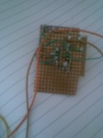
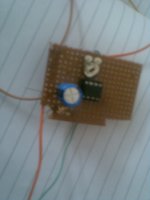
2. can you post a photograph of your wiring and contruction?
1. How do you know its oscillating? can you tell us what you here as you rotate the volule pot from min to max
2. can you post a photograph of your wiring and contruction?
Watch Your Gain
The LM386 has been out of production for many years, most likely because of oscillation issues. The TDA2003 is a good, cost effective, replacement. I've had many LM386's self-destruct on me, as their overcurrent and overtemp protection systems will not stop oscillation. Many people run these amplifiers above the maximum guaranteed stable gain of V X 10 and oscillation inevitably results. Place an op amp ahead of the LM386 if voltage gain above 10 is needed.
The LM386 has been out of production for many years, most likely because of oscillation issues. The TDA2003 is a good, cost effective, replacement. I've had many LM386's self-destruct on me, as their overcurrent and overtemp protection systems will not stop oscillation. Many people run these amplifiers above the maximum guaranteed stable gain of V X 10 and oscillation inevitably results. Place an op amp ahead of the LM386 if voltage gain above 10 is needed.
its working totally fine with the headphones (no oscillation, no distortion, awesome bass on the HD212 Pros, super-awesome), cool results, the speaker i was previously using was 4ohms 5 watts, my headphones are working cool.my layout is still crappy, but its working fine.am thinking of extending it to stereo input + output. just that there is a little noise i'd not want to have.
i've attached the pics bonsai, but the circuit's now working fine. thanks for ur support guys...
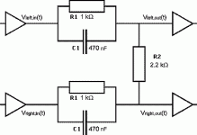
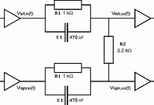
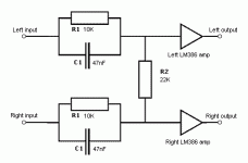
also, would a crossover work well with this lm386 setup??? schematic attached
i've attached the pics bonsai, but the circuit's now working fine. thanks for ur support guys...
also, would a crossover work well with this lm386 setup??? schematic attached
Attachments
Sorry, Total Error
Sorry folks, I got the numbers wrong. My info applies to the LM383 and not the LM386. I've used LM386's in several projects and never had stability issues. My bad on those type numbers.
The LM386 has been out of production for many years, most likely because of oscillation issues. The TDA2003 is a good, cost effective, replacement. I've had many LM386's self-destruct on me, as their overcurrent and overtemp protection systems will not stop oscillation. Many people run these amplifiers above the maximum guaranteed stable gain of V X 10 and oscillation inevitably results. Place an op amp ahead of the LM386 if voltage gain above 10 is needed.
Sorry folks, I got the numbers wrong. My info applies to the LM383 and not the LM386. I've used LM386's in several projects and never had stability issues. My bad on those type numbers.
In addition to the small ceramic decoupling cap, place an electrolytic (10 to 100 microF) also. The ceramic should be as close as possible to the chip, with the electro as close as possible to that. The speaker ground should connect directly (as close as possible to) to the ground leg of the electrolytic for truly effective decoupling of speaker current, which is the point of this really.
They don't have to be, but it looks better and stops the leads bending over and touching each other.do capacitor and resistor legs protruding out need to b chipped off?
Oh good, I love when stuff fixes itself while I'm asleep. 😀putting a 0.1 microfarad cap between the V+ and ground worked a charm.
The LM386 can't give much power into 4 ohms without distorting badly. Small 9V batteries (pp3?) also can't give much power - their voltage drops a lot when you draw too much current. A bigger 9V battery (pp9?) would be better. Headphones aren't a problem due to their higher impedance and lower power requirements.but then there's a lot of distortion.
That looks like a "blend" circuit for headphones, not a crossover. It should work fine. You could use an opamp or emitter follower on the left and LM386 on the right. Actually, if you make the resistors 10 times bigger and the capacitors 10 times smaller, you don't need anything on the left.also, would a crossover work well with this lm386 setup??? schematic attached
i worship you godfrey  . Respect.
thanx guys.
but by putting resistors ten times bigger and caps 10 times smaller, i wont need another lm386? that'll give me stereo???
 . Respect.
thanx guys.
but by putting resistors ten times bigger and caps 10 times smaller, i wont need another lm386? that'll give me stereo???
hey godfrey, check this one:
http://www.diyaudio.com/forums/chip-amps/178507-headbanger-grounds-trouble.html#post2387438
tried extending the above schematic to stereo with 2 lm386, dint understand much, so went in to make a headbanger.i got oscillations.grounds trouble for sure.please help.
http://www.diyaudio.com/forums/chip-amps/178507-headbanger-grounds-trouble.html#post2387438
tried extending the above schematic to stereo with 2 lm386, dint understand much, so went in to make a headbanger.i got oscillations.grounds trouble for sure.please help.
Do you have a power supply decoupling cap between V+ and GND? You need one, but it isn't shown in the schematic.
I would definitely agree.
Amplifiers with poor decoupling can get modulation of the power supply which is passed back to the input stage and it becomes an oscillator.
100nf and 100uf.
- Status
- Not open for further replies.
- Home
- Amplifiers
- Chip Amps
- lm386 oscillation

