Hi !
Long time I read this fantastic DYA forum and lern so much. But this is my first post, my English is too poor, sory !
10 minutes ago I finished first haf of regulated PSU and try it.
My tor. trafo from old amp is 2 x 41 V ,to high. After rec. and cap I hawe 61 V, on reg. output - 30V. It work, this is good thing.
Problem is - R1, 2.2K 2W after 1 minute of work is wery,wery hot. I think 61V is too much.
What walue of R1 need for tfis voltage, or samthing diferent way ?
Whatfor is R1? Mayby simply eleminate it ?
Zigis.
Thank You, Carlos for reply !
Wen I try new PS, I partly use old PS board width diodes and small ceramic caps. This give my output 41 V.
Now I desolder trafo and find 2 pairs of 2 x 24 V, twisted midlpoint. So, I think, I must use 1 half of each pair. So, I will get 2 x 24 independent. Ather half of each pair remind unused.
Is 24 V too low for 30 V reg. ? If so,wich R must chainge to lower V out.?
Zigis.
Zigis said:Is 24 V too low for 30 V reg. ? If so,wich R must chainge to lower V out.?
Zigis.
Yes, it's too low. You can regulate for around 24V.
You can use 100R for R3/R4 and 1.8K for R5/R6.
Or don't regulate, and you'll get around +/- 33V. With that trafo I would not regulate.
Zigis said:Now I desolder trafo and find 2 pairs of 2 x 24 V, twisted midlpoint. So, I think, I must use 1 half of each pair. So, I will get 2 x 24 independent. Ather half of each pair remind unused.
Hi Zigis,
If you can unwind the "twisted midlpoint" so you'll get 2 independant secondaries. You can then wire them in parallel to get double the current capacity.
regards
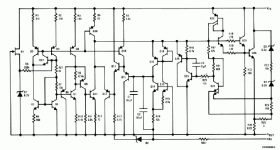
lineup said:Cant 30 VDC be made
in a more simple way,
than using 27 Transistors ?
🙂
This is the number inside LM388.
See schematic - and this is a simplified diagram!
You can say that for most linear regs.
It has 3 legs to the outside world, it's fairly cheap, very reliable, and good performance.
Thank You, Carlos.
Greg, I think abaout this way too,I am litle afraid to broke som wires, that is an old russian trafo.
I have 2 way - high cap unreg , or unwind and reg. Enyway I need parallel windings,to get full power.
Zigis.
Greg, I think abaout this way too,I am litle afraid to broke som wires, that is an old russian trafo.
I have 2 way - high cap unreg , or unwind and reg. Enyway I need parallel windings,to get full power.
Zigis.
is 55 volts too high to be used with this circuit?
I found a 2x55 volt 350VA toroid that I'd like to use with this snubber and the audiosector LM4780 Amplifier Kit.
I found a 2x55 volt 350VA toroid that I'd like to use with this snubber and the audiosector LM4780 Amplifier Kit.
zenon said:is 55 volts too high to be used with this circuit?
I found a 2x55 volt 350VA toroid...
That trafo will give you around 2x77V DC, waaay too much.

Hi !
I still tray to make my PS.
I hawe 25V AC at each rail.
First rail hawe 32V on C1 and 30V output.I now,ther is too small headroom,but it work.
Second rail have 28V on C1 and 25V output.Wen I disconect reg.,on C1 is 32V.
I doble chek evrything,but can not find mistake.
Help !
Zigis.
I still tray to make my PS.
I hawe 25V AC at each rail.
First rail hawe 32V on C1 and 30V output.I now,ther is too small headroom,but it work.
Second rail have 28V on C1 and 25V output.Wen I disconect reg.,on C1 is 32V.
I doble chek evrything,but can not find mistake.
Help !
Zigis.
@ carlosfm
Thanks for the schematic. I've just etched a PCB for your regPSU (basing on the Eagle file kindly shared by Tobias) and I'm now trying to figure out which parts I'll have to order.
When you updated your schematic back in August, you changed this:
330nF from V+ to V- pins
0.47R/1W + 47nF snubbers just before these caps
to this:
3.3µF from V+ to V- pins
0.1R/1W + 3.3nF snubbers just before these caps
In revision 1.1, I found the 0.47R resistor and the 47nF cap in the schematic and thought (erroneously?) that these were the parts that you mentioned in the text. In revision 1.2, the schematic stayed unchanged, but the values in the text have changed. Does that mean that the parts in the schematic and the parts mentioned in the text are not identical and that I have to add another R and C on the GC board?
I must admit that I'm a bit confused as to which part goes where.
Where do I place the 3.3µF from V+ to V- pins? Which pins?
I hope that you can help me with that. Thanks.
Peter
did Portugal win something in the Olympics?Nuuk said:Carlos will answer when he has stopped celebrating. 😀
Nuuk said:Carlos will answer when he has stopped celebrating. 😀

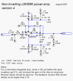
jpg said:Where do I place the 3.3µF from V+ to V- pins? Which pins?
Seems like your are watching only one part of the movie.
Here's the amp.
Yes, there are snubbers on the amp board too, and the 3.3uF film cap goes between the voltage rails (V+ to V-).
Attachments
jackinnj said:did Portugal win something in the Olympics?
No, Benfica beat Liverpool.
Football (you call it soccer, right?).
OK,
I know Carlos has little patience for guys like me so I will pose this question to anyone and hope for a willing DIYer, not that Carlos isn't...
I am interested new to this world but I am building my second LM4780 amp. Actually, it is 2 LM4780 chips paralleled per channel. I am interested in regulating and snubberizing the entire amp.
Each channel will be running off of a 400VA 22V Transformer for the two chips in each channel.
QUESTION: Which (if any) snubber network/regulated power supply should I use from Carlos' vast collection?
I have found quite a few that he has put out there!LOL
Thanks,
Dominick
Dominic, it's not that Carlos has 'little patience', more than he doesn't have an infinite amount of time to try every possible combination of snubber values! 
He has shown enough here to allow people to try different values and see if they are better or worse for themselves.
For your application, you could start off with any of the snubberised PSU's that Carlos has published and then try tweaking them by changing resistor or cap values. 😉
He has shown enough here to allow people to try different values and see if they are better or worse for themselves.
For your application, you could start off with any of the snubberised PSU's that Carlos has published and then try tweaking them by changing resistor or cap values. 😉
Thanks nuuk,
I didn't mean to imply that "little patience" was a negative cut-down. I simply meant that I realize many people are lobbying for his attention and I would probably just be another nagging newb.
You say try any of the snubs/power regulators...
but which are most current?
If someone could reply with the 2 schematics that would be best suited for my application...I would be very thankful.
Since I am still learning, it is very difficult for me to make any sort of educated decision. I would be drawing a number out of a hat!
Hoping,
Dominick
- Status
- Not open for further replies.
- Home
- Amplifiers
- Chip Amps
- LM338 regulated snubberized PSU for audio amplifiers