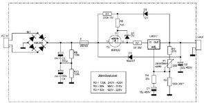
The IRF820 is going to handle the brunt of the voltage drop. How much current do you plan to draw, what's your raw B+, what will be your regulated voltage?
In this circuit there will be about 8V over the LM317 (12V zener - Vgs for enhancement mosfet).
Power dissipated on IRF820 is
(Vin-Vout-8)*I
example:
Vin 350
Vout 300
Current 100mA
(350-300-8)*0.1 = 3.8W
Power dissipated on Lm317: 8V * 0.1A = 0.8W
missed the 33 ohm resistor. At 100mA thiw will dissipate 0.33W, and the LM317 about 0,5W.
Power dissipated on IRF820 is
(Vin-Vout-8)*I
example:
Vin 350
Vout 300
Current 100mA
(350-300-8)*0.1 = 3.8W
Power dissipated on Lm317: 8V * 0.1A = 0.8W
missed the 33 ohm resistor. At 100mA thiw will dissipate 0.33W, and the LM317 about 0,5W.
Hi dotneck335
why do you think that?
what I dont like much about the 317 in this application is that a 317 requires 5mA, some say 10mA load, to regulate well. At 300V output that is 1.5W (5mA), a potentiometer that can take that is quite big, expensive and probably not very reliable. There is a recent thread on the LT3080 - I would probably use that device if I were to build one of these regulators.
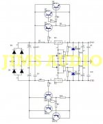
I think this is a better design for a high voltage/high current regulator.
High current - yes, with the drawbacks that the power devices' emitter balancing resistors are missing and that there's no overload protection at all.
High voltage - no, the input voltages mustn't exceed the LM317's/LM337's ratings.
Best regards!
The LM317/337 datasheet does NOT indicate a maximum input OR output voltage---only that the DIFFERENCE must be less than 40 volts.High voltage - no, the input voltages mustn't exceed the LM317's/LM337's ratings.Best regards!
You are right but the problem is that at power up the output capacitor appears as a near short to 0V
I your mind is not definitely set on using a 317, here is a discrete alternative.
It might be a bit more complex, but certainly not more expensive and offers similar performances.
The main advantage is a vastly improved ruggedness in real life situations, but it is also more frugal, wastes less dropout voltage and offers a higher level of flexibility.
Simple HV series regulators
It might be a bit more complex, but certainly not more expensive and offers similar performances.
The main advantage is a vastly improved ruggedness in real life situations, but it is also more frugal, wastes less dropout voltage and offers a higher level of flexibility.
Simple HV series regulators
Si à zener is a must across Vin and Vout.You are right but the problem is that at power up the output capacitor appears as a near short to 0V
Yeah, I've always thought that adding a 40 volt Zener across the in & out terminals of the 317/337 would be a good idea. I've not blown up a 317 without it, but it sure has happened to me with LT1083s.You are right but the problem is that at power up the output capacitor appears as a near short to 0V
Well, the emitter resistors aren't really needed if you beta-match the pass- transistors.High current - yes, with the drawbacks that the power devices' emitter balancing resistors are missing and that there's no overload protection at all.
- Status
- Not open for further replies.
- Home
- Amplifiers
- Power Supplies
- LM317 HV PSU