Search in the National Semiconductor or ST datasheets, there are lots of data. In any case, a couple of resistances is what you need for those IC to put them working for you.
Grande el Nano, uno de mis preferidos.
Grande el Nano, uno de mis preferidos.
I see this web calculator LM317 LM337 Voltage Regulator Calculator, for R25-27 using 5K trimmer I get +-24V, is OK & gives 200mA?
An externally hosted image should be here but it was not working when we last tested it.
An externally hosted image should be here but it was not working when we last tested it.
Last edited:
Fine, perfect. I only suggest to make only a few % variable, not from rail to rail because potentiometers becomes noisy when DC flows trough them. In this case, I would use 4.7 fixed plus, say 500R variable, in the ground leg.
In place of trimmer a fixed resistor of 4K7 + 500 ohms trimmer, right?
Who is: Grande el Nano, uno de mis preferidos?
Who is: Grande el Nano, uno de mis preferidos?
Yes!In place of trimmer a fixed resistor of 4K7 + 500 ohms trimmer, right?
Who is: Grande el Nano, uno de mis preferidos?
El Nano Joan Manuel Serrat.
I was born in Barcelona like El Nano🙂
I like all his songs in Spanish & in Catalan too.😉
I don't understand Catalá, but I like almost all his songs like Pueblo Blanco, Mediterráneo, and Paraules d'amor.
Also like J. Sabina singer songwriter.
Could I use 47uF for C19, C20, C22 & C23? & 220R or 270R for R24 & R26?
Ola` Merlin,
yes and yes, but is better to use protection diods like data sheet shows to play safe.
ciao
marco
Ola` Merlin,
yes and yes, but is better to use protection diods like data sheet shows to play safe.
ciao
marco
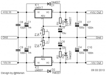
Split supplyes usually have theyr schematics designed mirrored, the reason is obvious. This is what should be done as in the immage attached, C1 and C2 i suggest they should be at least 1m ( that is 1000u ), you want as little ripple as possible at Vin for the reggs, and 1m caps are easy to get by and cheap enough. C5 and C6 makes it possible to get lower ripple on the outputs but to use them is mandatory to have D3 and D4 witch in case of a shorted output protects the regulator from capacitor discharging in the Adj pin. D1 and D2 are also mandatory, they ensure that in case of a power supply failyure, output capacitors C3 and C4 will not discharge in the output pins of the regulators destroying them. The 100n caps are needed for high freq noise supression, they handle it better.
LM317 and it's cousin LM337 deliver a max current of about 2,2A, and a medium one of about 1,5A, both situations depend verry much on the Vin-Vout differencial, for maximum efficiency you must make sure that differencial will stai in the range of 4 to 11V, meaning that for example at 24V output needed you must make sure that Vin will be between 28 to 35V, that way you get the smallest stress you can assure for the regulator and the maximum efficiency possible in this configuration. Obviously you will need some minimum heatsinking for the reggs, especially for bigger Vin-Vout differencial.
LM317 and it's cousin LM337 deliver a max current of about 2,2A, and a medium one of about 1,5A, both situations depend verry much on the Vin-Vout differencial, for maximum efficiency you must make sure that differencial will stai in the range of 4 to 11V, meaning that for example at 24V output needed you must make sure that Vin will be between 28 to 35V, that way you get the smallest stress you can assure for the regulator and the maximum efficiency possible in this configuration. Obviously you will need some minimum heatsinking for the reggs, especially for bigger Vin-Vout differencial.
Attachments
Last edited:
Could I use 47uF for C19, C20, C22 & C23? & 220R or 270R for R24 & R26?
Ola` Merlin,
yes and yes, but is better to use protection diods like data sheet shows to play safe.
ciao
marco
Split supplyes usually have theyr schematics designed mirrored, the reason is obvious. This is what should be done as in the immage attached, C1 and C2 i suggest they should be at least 1m ( that is 1000u ), you want as little ripple as possible at Vin for the reggs, and 1m caps are easy to get by and cheap enough. C5 and C6 makes it possible to get lower ripple on the outputs but to use them is mandatory to have D3 and D4 witch in case of a shorted output protects the regulator from capacitor discharging in the Adj pin. D1 and D2 are also mandatory, they ensure that in case of a power supply failyure, output capacitors C3 and C4 will not discharge in the output pins of the regulators destroying them. The 100n caps are needed for high freq noise supression, they handle it better.
LM317 and it's cousin LM337 deliver a max current of about 2,2A, and a medium one of about 1,5A, both situations depend verry much on the Vin-Vout differencial, for maximum efficiency you must make sure that differencial will stai in the range of 4 to 11V, meaning that for example at 24V output needed you must make sure that Vin will be between 28 to 35V, that way you get the smallest stress you can assure for the regulator and the maximum efficiency possible in this configuration. Obviously you will need some minimum heatsinking for the reggs, especially for bigger Vin-Vout differencial.
Many thanks guys🙂
- Status
- Not open for further replies.
- Home
- Amplifiers
- Power Supplies
- LM317-337 regulated +-24VDC
