Hi All!
I'm designing a buck-regulator, which will have to produce 5V @ 6A from 25V DC.
There will be biult more of this circuit, so the circuit must be simple (low component count), and cheap(as always 🙂 ).
I use LM2574-ADJ, as a PWM-controller. But it can deliver only 0.5A, so I have to use this IC only as a pwm-controller, and this IC must control a high-side, and a low-side MOSFET.
I drew a high-side floating MOSFET-DRIVER from discrete transistors. This schematic works in the simulator, and hopefully, it works in the real life.
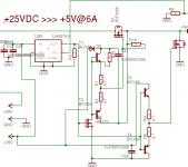
My problem is with the LM2574-ADJ IC. When I connect the IC, as the IC was originally designed (the IC 's output is connected to an inductance, etcetc), then the IC works perfectly. But when I connect the IC 's output to my high-side and low-side FET-driving transistors, then the IC doesn't work 🙁 At the IC's output I see on my 'scope only small (about 1.7-2V high) spikes, nothing else. See the attached image for the schematic!
What can be the problem?
thanks in advance! 🙂
edit: on the attached image, there are IRF3205 FETs, but I used instead of them IRF540. The circuit must deliver 5V, and I used LM2574-ADJ, becouse in the completed stuff there will be another dc/dc converter,wich have to produce 24V/5A, and that requires the same circuit. (ofcourse, the input voltage will be higher)
I'm designing a buck-regulator, which will have to produce 5V @ 6A from 25V DC.
There will be biult more of this circuit, so the circuit must be simple (low component count), and cheap(as always 🙂 ).
I use LM2574-ADJ, as a PWM-controller. But it can deliver only 0.5A, so I have to use this IC only as a pwm-controller, and this IC must control a high-side, and a low-side MOSFET.
I drew a high-side floating MOSFET-DRIVER from discrete transistors. This schematic works in the simulator, and hopefully, it works in the real life.
My problem is with the LM2574-ADJ IC. When I connect the IC, as the IC was originally designed (the IC 's output is connected to an inductance, etcetc), then the IC works perfectly. But when I connect the IC 's output to my high-side and low-side FET-driving transistors, then the IC doesn't work 🙁 At the IC's output I see on my 'scope only small (about 1.7-2V high) spikes, nothing else. See the attached image for the schematic!
What can be the problem?
thanks in advance! 🙂
edit: on the attached image, there are IRF3205 FETs, but I used instead of them IRF540. The circuit must deliver 5V, and I used LM2574-ADJ, becouse in the completed stuff there will be another dc/dc converter,wich have to produce 24V/5A, and that requires the same circuit. (ofcourse, the input voltage will be higher)
Attachments
Hi Danko !
So after all you changed the pwm chip.
As you know, for driving a npn bipolar transistor or a n-channel mosfet in a buck topology you need a floating voltage. Because of that, the circuit complexity increase and of course the costs too.
If you dont want to use a level shifter bootstrap solution you can try to use a transformer to drive the power switch, but for minimum number of components you can use a pnp transistor or a Darlington with pnp's (for high current) or you can use a p-channel mosfet (or several in parallel). This simplify your driver circuit.
Sorry I don't have experience with LM2574.
hello!
finally, i solved the problem. After eht LM2574's emitter i put a pull-down resistor, and a CD4049. The first gate's output goes to the BS170's GATE. After this, I infert twice the signal, and the last few gates are connected paralell, and they drive the low-side MOSFET (IRF540N).
Here are some picture of the low-side MOSFET's GATE:
http://sziget.mine.nu/~danko/aramkor/testbed/10/fet_drive/
- Status
- Not open for further replies.