Hi all,
I am currently working on implementing LM1876 based amp and ran into the issue with the mute and standby pins.
From the datasheet, if a logic high (1.5 to 5V) is applied to the MUTE pin, the amp will be muted.
The goal is to mute the amp during the turn on (and turn off).
For that a logic high needs to be applied to the MUTE pin when amp is turned on, but after 1 or 2 seconds wait time the MUTE pin should be pulled low (< 1.5V).
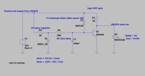
I have come up with a simple simulation circuit that consists of :
Power is taken from the positive rail of the amp's power supply that is 20V to 25V.
Zener regulator resistor is selected at 1K, and it pulls about 20mA of current.
Any suggestions on improvement will be appreciated.
I am currently working on implementing LM1876 based amp and ran into the issue with the mute and standby pins.
From the datasheet, if a logic high (1.5 to 5V) is applied to the MUTE pin, the amp will be muted.
The goal is to mute the amp during the turn on (and turn off).
For that a logic high needs to be applied to the MUTE pin when amp is turned on, but after 1 or 2 seconds wait time the MUTE pin should be pulled low (< 1.5V).
I have come up with a simple simulation circuit that consists of :
- 5V zener regulator
- RC time delay
- NOT logic gate
Power is taken from the positive rail of the amp's power supply that is 20V to 25V.
Zener regulator resistor is selected at 1K, and it pulls about 20mA of current.
Any suggestions on improvement will be appreciated.
Attachments
Last edited:
First thoughts...
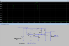
You need such a big timing cap because you are only charging it to 0.6 volts and so not using most of the available curve. I would swap the transistor for a power FET (small 2N7000 type) as that will allow a much smaller cap because of the high gate/source voltage to turn on. Make the Zener a wee bit higher voltage, say 8.2 volt and increase the 30k.
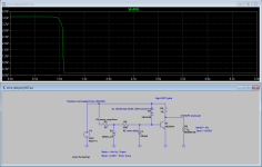
A rapid switch off might be a problem if powered from slowly collapsing main rails. In simulation it shows the chip unmuting as the rail collapses. The easiest ways to stop this are to detect the C on the secondary and apply an instant mute when the AC drops out.
If you make the supply 'a pulse' you can set rise and fall times of the supply to simulate power on and off.

You need such a big timing cap because you are only charging it to 0.6 volts and so not using most of the available curve. I would swap the transistor for a power FET (small 2N7000 type) as that will allow a much smaller cap because of the high gate/source voltage to turn on. Make the Zener a wee bit higher voltage, say 8.2 volt and increase the 30k.
A rapid switch off might be a problem if powered from slowly collapsing main rails. In simulation it shows the chip unmuting as the rail collapses. The easiest ways to stop this are to detect the C on the secondary and apply an instant mute when the AC drops out.
If you make the supply 'a pulse' you can set rise and fall times of the supply to simulate power on and off.
Attachments

Thank you, will play with those values.
What do you mean by "detecting the C on the secondary"?
Any suggestions for more affordable FET?
What do you mean by "detecting the C on the secondary"?
Any suggestions for more affordable FET?
Its missing an A, detect the AC.
Hmmm 😉 not really.

Any suggestions for more affordable FET?
Hmmm 😉 not really.
KiCAD 5 open source code for the circuit can be found on GitHub - https://github.com/pavel-bilous/LM1876_mute
Reason for 5V zener regulated voltage is to use it to actuate standby mode of the chip. It can be done simply by applying 5V to the STANDBY pin of the LM1876.
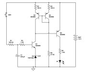
Just came across a circuit that makes bjt transistors work as a delay by putting zener diode between npn emitter and gnd. In that way 0.6v threshold is raised by whatever voltage is desired, in turn allowing for smaller capacitor values.
ps: in the circuit there is a current mirror and buffer stage that in my opinion overkill.
ps: in the circuit there is a current mirror and buffer stage that in my opinion overkill.
Attachments
Using a Zener/LED/Diodes to lift the emitter is a very useful trick. These days a MOSFET is another option, it has a high gate threshold of a few volts and almost infinite input impedance which even allows the use of small film caps as the timing element used alongside high value charging resistors if the delay needed is not to long.
- Home
- Amplifiers
- Chip Amps
- LM1876 mute pin delay circuit in LTSpice