Hi to all,
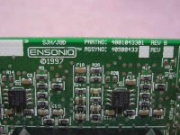
This soundcard is an old (~1997) Ensonic AudioPCI E1370 which has a separate board for an LM1876 power amplifier.
It is powered from the +12V (4.2A) and -12V lines (0.8A) of the PC PSU.
Looking at the datasheet for the LM1876, here, i see the LM1876 can only give ~8W at +/-12V.
So what mods can be done to the board/PSU to increase power output from the LM1876:
1) Can the +5V and +12V, and -5V and -12V lines of the PSU be joined to to give +/-17V?
2) if 1 is not possible, can the +5V and -12v, and -5V and +12V be combined to give +/-17V? will the low current of the -5v line (~0.3A) be a problem?
3) Change rectifiers of -12V line to give higher current to match the +12V line of the PSU? Will this make any difference, since the LM1876 will still draw the same current as before at -/+12V?
4) Can anything else be done to increase the voltage from the PSU above +/- 12v? (increase power to pin1 of the tl494 pwm regualtor IC of the PSU. etc?)
ta
Attachments

Nothing can be done. It has inadequate capacitance, heatsinking, and current from the negative PSU rails to support higher wattage. That it has an amp chip capable of higher output is somewhat irrelevant, you would be better off building a new amp from scratch.
No you cannot join the +-5V and +-12V rails to end up with +-17V. No you cannot do some other odd thing mentioned as #2 to end up with +-17V either, at most you would end up with a +12V to -5V, 17V total difference instead of +12V to -12V, 24V total difference, PLUS you would have a problem with +12V and -5V (and/or -12V and +5V) in that system ground is not centered between the two rails at 0V.
No, modifying the PSU rectifier will not matter, that will not increase power production on that rail.
No you do not want to increase PSU voltage much beyond +-12V because this is needed for the PC operation.
HOWEVER, if you really want to hack it, here is what to do:
1) Remember your upper voltage limit is determined by the two opamps, (formerly JRC but now NJM) NJM4565. Their upper limit is +-18V. Instead of plugging a connector between sound card and amp board for power, use add-on transformer, bridge rectifier, and capacitors. This is required, to add a separate PSU to get higher voltage.
2) Replace the two electrolytic capacitors with some of higher capacitance, and they might only be rated for 16V too. If your off-board power supply has sufficient capacitance you may not "need" to increase their capacitance value, only to make sure their voltage rating is high enough.
3) Remove stock heatsink and put a better one on. How you mount that is going to be the tricky part, anything suitable would have enough mass that it should not rely only on the chip pins, should be mounted to the board or bracket somehow (or maybe the existing heatsink was, but I cannot see this detail being present in the picture).
4) Replace the speaker output jacks with proper terminals, headphone jacks are not suited to high power output.
Realistically, I don't think this amp module is worth the trouble. Considering that the module is probably about a dozen years old, I would just swap in new, low ESR capacitors of the highest capacitance you can get to fit considering how close they are to the heatsink clip and the PCB lead spacing.
Last edited:
Thank you ! for the informed reply. much appreciated.
I forgot to mention one thing in my first post- that is, the chip and PSU are salvaged parts from an old computer and it is no longer used in the PC.
So the PSU can be completly gutted and rewired if required. I really do not want to build another PSU from ground up since this PSU is just lying around with no use.
I can change the heat sink and caps on the chip board without much trouble.
The problem lies in getting the required current and voltage from the PSU. I read on another post that pin1 of the tl494 regulator chip of the PSU can be modded to get around -/+18v output from the PSU. Article is here.
Can this be done? Change the supply to -/+18v as in the article and then change the rectifiers of the -18v side to match the high current of the +18v side???
ta
Yes the power supply can be modded. But it involves some knowledge of switching supplies and you will most likely blow it up first. 😛 In essence all you need is to find the feedback pin (either pin 1 or 16 will be used) and connect a pot between it and ground, that will allow you to adjust voltage. However, the transformer may not have enough headroom to provide 18v at low mains while keeping regulation, so you could end up with hum, oscillations and similar issues. You will also need new capacitors for the former 12v and -12v rails in the power supply because the original ones can't take more than 16v.
Plus, negative rails on PC supplies are always very weak, simply because all they've been used for during the whole history of the PC was bias voltages. It's not only the rectifiers but also the wiring on the coil. For that little chip i'd just buy a small mains transformer and call it a day... switching PSUs become worthwhile when we're talking more than 300W.
Plus, negative rails on PC supplies are always very weak, simply because all they've been used for during the whole history of the PC was bias voltages. It's not only the rectifiers but also the wiring on the coil. For that little chip i'd just buy a small mains transformer and call it a day... switching PSUs become worthwhile when we're talking more than 300W.
Last edited:
How about intercepting the signal feed into the chipamp and bringing this/these to become line outputs? Then doing the power amp properly outside the PC chassis.
one more thing,
I heard some PC PSUs have muliple +12V power rails. If mine does (i will check), can the rectifiers of one rail be moded to get -12v instead, at the rated current of the +12v rail(i.e.: 4.2A)?
I heard some PC PSUs have muliple +12V power rails. If mine does (i will check), can the rectifiers of one rail be moded to get -12v instead, at the rated current of the +12v rail(i.e.: 4.2A)?
The multiple rail PSUs use the same transformer and the same inductor winding, they simply use several current shunts for monitoring, to avoid overloading the cable that is wired to them. If they used a separate winding on the inductor it could've been modded. Or if you're willing to add your own winding on the output toroid. Remember, for a negative voltage it has to be wired the other way round.
Some modern, semi-expensive ATX12V PSU do have a 2nd winding for 3rd, 4th, 12V rails that could have one of those transformer windings desoldered at the ends and reverse connected but I hardly see the point in buying one, not cost effective... even if you had one it is worth more for use or resale as a computer power supply.
ok, I will use the amp as it is with +/-12V since modifying is too much work for little gain.
The amp will run with +12V @ 4.2A and -12V @ 0.8A. Does it mean the amp is using only 0.8A max from both rails? And the max power consumption would be roughly (24V x 0.8A) = 19.2W ?
What if the current on the -12V was also increased (in someway) to 4.2A. Would the chip consume more power then or still draw less than 0.8A same as before? may be have less distortion since more current is now suddenly available?
ta
It means the power supply is capable of 800mA on the -12 V supply and when you exceed that (VERY easily) something will go into 'protect' or may just fail. Asymmetrical power supply current will cause some bizarre distortions as the positive supply stays steady and the negative 'comes and goes'.
The chip will only draw whatever current is required for the signal and load combination. Higher signal = more current. Lower ohms load = more current = more problems.
G²
The chip will only draw whatever current is required for the signal and load combination. Higher signal = more current. Lower ohms load = more current = more problems.
G²
If the negative rail goes very low the amp may draw more from the positive and get DC offset at the output. However i think the power supply will not allow it to go very low, when it shuts down you'll know why.
If the current would be increased the chip will of course draw more power (and supply more power to the speaker) if it's called for.
If the current would be increased the chip will of course draw more power (and supply more power to the speaker) if it's called for.
if the -ve supply is limited to 400mApk and there is little decoupling on the sound card PCB then the maximum output current will be ~-800mApk.
The maximum power into a 4ohms speaker will be limited to ~ 0.8V^2 * 4ohms / 2 = 1.28W.
If you connect an 8ohm speaker the maximum power output rises to 2.56W.
This assumes the sound card uses no current and the whole 8-00mApk is available to meet the current demand of the speaker.
The maximum power into a 4ohms speaker will be limited to ~ 0.8V^2 * 4ohms / 2 = 1.28W.
If you connect an 8ohm speaker the maximum power output rises to 2.56W.
This assumes the sound card uses no current and the whole 8-00mApk is available to meet the current demand of the speaker.
Last edited:
AndrewT
Not sure what you mean when you say 'if the -ve supply is limited to 400mApk...then the maximum output currrent will be ~-800mApk' ???
The -12V rail is rated at 0.8A max (and the +12v rail is rated at 4.2A)
So do you mean that the total output current will be (0.8Ax2) 1.6A ???
From this the max power into 8 Ohms per channel will be P= I^2 * R /2
which is (1.6A^2 * 8)/2 = 10.24 W (max per channel roughly)
Is this correct ???
Hi DMX.
I would first check to see if the LM1876 is configured to run on a single ended power supply. IMO this is the most likley configuration due to the voltage rails available from common PC power supply. And also realise that the LM1876 will not swing rail to rail so the max output voltage will be lower by at least 3 volts .
Regards Ian
Last edited:
no. Both my answer and your interpretation are wrong.Is this correct ???
Thinking about it again, if the -Ve supply is limited to 400mA then the maximum demand of the load must also be limited to the same 400mApk, not the 800mApk quoted earlier.
For a symmetrical AC sinewaveform, that limits the output power and output voltage to minuscule values.
where does 400mApk come from??? It is rated at 0.8A at -12V so it should be 800mApk on the -ve rail and similarly in the +ve rail ...isnt it?
So the max current from both rails is 1.6A??
So the max current from both rails is 1.6A??
Last edited:
Worst case (very low frequencies, buffer cap doesn't do much):
-12V @ -800mApk (~=-283 mArms), hence 1600mApp ~= 566mArms max (~= 2.5W @ 8 ohms or 1.25 W @ 4 ohms)
Best case (high frequencies, peaks entirely absorbed by buffer cap):
-12V @-800mArms, so you get 1600 mArms total max (~=20 W @ 8 ohms, except you won't get more than 6..7 W on +/-12V, so 10 W @ 4 ohms is more likely to be it)
Now considering where most power is commonly needed - in the bass - the importance of adequately sized buffer caps becomes obvious.
Basically I can see two options here:
1. Give the '1876 a new PCB, heatsink and power supply, which should yield a nice 2x 20 W power amp.
2. Reduce gain to maybe 10..14 dB (with a small cap across the inputs to keep it stable, usually double digit pF range) and use it as a competent headphone driver. Maybe the gain already is set no higher than 20 dB, I don't know.
- Status
- Not open for further replies.
- Home
- Amplifiers
- Chip Amps
- LM1876 from a pc souncard - Can it be moded?