I have been building amps/preamps for years, mostly tube but not all. I built my first chipamp (LM3886) a few months ago and it sounds great. I used the datasheet schematic.
I decided to make one with LM1875 chips just for the heck of it. Power is not an issue, my main speakers have 104db sensitivity.
I was planning on using the datasheet schematic for the LM1875 but was wondering if there are any changes to the datasheet schematic that may improve the sound. I am aware of the AN-1192 paper.
(Yes I know this is very subjective)

I am planning on an 18-0-18 transformer so about plus and minus 25vdc.What supply voltage will you use?
Post in thread 'Various stuff free or for sale' https://www.diyaudio.com/community/threads/various-stuff-free-or-for-sale.392629/post-7221935
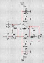
Here is my suggestion for LM1875 with +/-25V supply.I am planning on an 18-0-18 transformer so about plus and minus 25vdc.
I use 47k resistors.
Attachments
If you built the 3886 amp already….lm1875 amp will not sound that different.I have been building amps/preamps for years, mostly tube but not all. I built my first chipamp (LM3886) a few months ago and it sounds great. I used the datasheet schematic.
I decided to make one with LM1875 chips just for the heck of it. Power is not an issue, my main speakers have 104db sensitivity.
I was planning on using the datasheet schematic for the LM1875 but was wondering if there are any changes to the datasheet schematic that may improve the sound. I am aware of the AN-1192 paper.
(Yes I know this is very subjective)
You could try Mauro Penasa RIP MyRef Lm3886 pump or Tom’s modulus86 amp.
I am not expecting it to have much difference. I really am just going to build it out of curiosity and possibly tweaking. I am familiar with the two amps you mentioned.If you built the 3886 amp already….lm1875 amp will not sound that different.
I guess you know this thread: https://www.diyaudio.com/community/...ion-and-used-in-a-composite-amplifier.346645/
I don't know the whole thread, but there are some working composite amp examples, such as #653 (that's a very similar tda 2050 version, however).
I don't know the whole thread, but there are some working composite amp examples, such as #653 (that's a very similar tda 2050 version, however).
Is R3 the speaker load?Here is my suggestion for LM1875 with +/-25V supply.
Use factory.
The high pass capacitor C2 in voltage divider for gain can be slightly large if you want lower frequency response.
Not gonna change much already set to 3 Hz. Might measure lower distortion.
Usually just done in sim depending on the FFT used , people often make the cap larger since it lowers distortion in sim.
100uF or even 220uF, likely wont do much in real life.
Input resistor to ground is set to a specific value in factory to keep DC offset low on the output. R2
If you change the gain , input resistor typically needs to be 2 to 3k higher for DC offset.
Typically R2 and R4 would be same value in most amplifiers.
This case R2 is set slightly higher as mentioned for DC offset to be correct
Last edited:
This will be Unpopular But 🙂 Built an 1875 Amp a while back... Using First world parts ,using the Datata sheet Curcuit .
Carefully and precisely.
Even built a Torroid Power supply (no stone left unturned 🙂
The thing Sounds Decent ..But as even Elliot Sound stated Clearly : the LM1875 is a Good amp but it is NOT a 'high end' one .
All claims notwithstanding.
I didn't believe his statement . However In retrospect the man is 100% correct.
Not even close to my Bespoke Lm3886 amp.
Nor even in the Same room as My DIY Firstwatt.
But have fun.. nonetheless.
If you want to go with the composite amp route, there is a nice article in magazine " Radio Electronics Nov1992 " issue about using LM1875 in every ( single, parallel, bridge and bpa ) combination. There is a link to the pdf in following forum page;
While looking for completely different things, I found this old magazine by chance from November 1992
Radio Electronics (November 1992) : Free Download, Borrow, and Streaming : Internet Archive
and an excellent diy power amp project at hard to beat price with LM1875 and AD711 - go to the attached PDF file.
Are there more advanced versions in this topology with operational amplifier IC's from last generation like TI's OPA1611 or OPA1656 - go to
Burr-Brown OPA1611/1612 are here
together with traditional power amp ICs like LM3886 or TDA7293/TDA7294 ?
I am mainly interested in...
- tiefbassuebertr
- Replies: 14
- Forum: Chip Amps
- Home
- Amplifiers
- Chip Amps
- LM1875 optimal sound quality version