Hi everyone! I have always been interested in audio designs and always wanted to design an amp from the IC up. I finally did it and I bought 2x LM1875 chips.
The problem I am having is that at higher volumes is really distorting especially for bass and to some degree just treble.
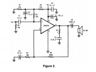
I am using this schematic from the Manuel itself (Figure 2.) since I don't have a split supply. Another issue I am noticing is that at higher VCC voltages it cuts out? I am not sure if the gain is too much or anything.
I am really new to this and I am very interested in learning and improving my skills on DIY audio systems.
The problem I am having is that at higher volumes is really distorting especially for bass and to some degree just treble.
I am using this schematic from the Manuel itself (Figure 2.) since I don't have a split supply. Another issue I am noticing is that at higher VCC voltages it cuts out? I am not sure if the gain is too much or anything.
I am really new to this and I am very interested in learning and improving my skills on DIY audio systems.
Attachments
at higher volumes is really distorting especially for bass and to some degree just treble.
Congratulations on getting this far on the first try, many don't.
The schematic seems ok, can you post photos of your pcb?
Are you sure that all the polarized capacitors are connected the right way?
Also, are you using a heat sink on the LM1875?
Last edited:
Thanks mate! I am not using an heatsink, however my input supply is 10 is suffice for a heatsink I believe. I am not home right now but will post soon. Thank you for the reply 🙂
Quoted from the same data sheet you got the schematic from :
POWER DISSIPATION AND HEAT SINKING
The LM1875 must always be operated with a heat sink, even when it is not required to drive a load. The
maximum idling current of the device is 100 mA, so that on a 60V power supply an unloaded LM1875 must
dissipate 6W of power. The 54°C/W junction-to-ambient thermal resistance of a TO-220 package would cause
the die temperature to rise 324°C above ambient, so the thermal protection circuitry will shut the amplifier down if
operation without a heat sink is attempted.
The 54°C/W junction-to-ambient thermal resistance of a TO-220 package would cause
the die temperature to rise 324°C above ambient, so the thermal protection circuitry will shut
the amplifier down ifoperation without a heat sink is attempted.
Bingo, that's pretty toasty. At least it doesn't require isolation.
I agree with the heatsink but it's that serve enough to cause distortion at volumes a litttle bit over half on an iPhone ?
A quote from this ESP page Single Chip 25W Amplifier (Project 72) :-
Never operate these ICs with no heatsink, even without any load connected. The quiescent dissipation will cause them to overheat very quickly, and may damage the internal circuitry.
Never operate these ICs with no heatsink, even without any load connected. The quiescent dissipation will cause them to overheat very quickly, and may damage the internal circuitry.
Because it's overheating........Another issue I am noticing is that at higher VCC voltages it cuts out?
I see. I have attached a heatsink and it no longer shuts off at 11v +, however the noise distortion is still there at high levels. The supply voltage is now 20v
You sure? I am pretty sure the chip has built in thermal overprotection as well... and I didn't run it at 10+ volts for long times maybe a couple of seconds
There is a chance the chip's circuitry is damaged (as mentioned in quote)
Likely, I'd just go ahead and replace both. It's a cheap lesson.
So I just check the brand new one. Same thing
Don't get discouraged, these things happen to most, if not all.
There's one way it works right, and many ways it works wrong.
Just makes me keep going. I am really intrigue by all this. Here is the picture boss LM1875 setyp - Album on Imgur
Just makes me keep going. I am really intrigue by all this.
Here is the picture boss LM1875 setyp - Album on Imgur
Solderless breadboards are appealing, but they must be used with great discretion.
Try much shorter solid interconnecting wires. Place the bypass capacitor C7 close
to the device pin. All the grounds should connect very near each other and the device.
Does the device run cooler now, or is it still hot, and maybe oscillating? Do you have a DVM?
Never work when you're rushed, tired, or upset. Bad things will happen.
Last edited:
Shorter wires got it.
Grounds closer got it. (The ground is PIN 3 right? really confused on this concept here.)
Bypass capacitor already next to chip (Pin 5).
I do have a DVM want me to check something?
The device runs cool now and its not oscillating the gain is greater than > 10
Grounds closer got it. (The ground is PIN 3 right? really confused on this concept here.)
Bypass capacitor already next to chip (Pin 5).
I do have a DVM want me to check something?
The device runs cool now and its not oscillating the gain is greater than > 10
Last edited:
- Status
- Not open for further replies.
- Home
- Amplifiers
- Chip Amps
- LM1875 Need help