hi members
Just completed a stereo channel LM1875 amplifier ... one of the channel is giving intermittent noisy hissing noise ... another side is dead quiet and silent ... the hissing noise comes and goes randomly and kinda sounds like when a radio on empty frequency station hissing noise ... but when music is playing the sound was not distorted ... only the annoying part is the hissing noise ... maybe is the IC itself having problem? pls help ... thx alot
Just completed a stereo channel LM1875 amplifier ... one of the channel is giving intermittent noisy hissing noise ... another side is dead quiet and silent ... the hissing noise comes and goes randomly and kinda sounds like when a radio on empty frequency station hissing noise ... but when music is playing the sound was not distorted ... only the annoying part is the hissing noise ... maybe is the IC itself having problem? pls help ... thx alot
check temperature of the ic, and double check soldering first.
then post pictures (good , sharp) of the finished build along with the schematic of the build.
otherwise its hard to help.
allso a closeup of the chips them selfs may reveal something usefull.
then post pictures (good , sharp) of the finished build along with the schematic of the build.
otherwise its hard to help.
allso a closeup of the chips them selfs may reveal something usefull.
Parasitic oscillation? Keep the input and output leads separated. Make sure the IC supply pins are bypassed with appropriate bypass capacitors. Verify proper grounding. Look at the output with an oscilloscope to see what is happening.
Ya forgot that I used paper caps 100nf for bypass the IC ... could it be the cause of the problem? But other channel tolerate well with it
It could be a cold solder joint. It could also be parasitic impedances on the board.
Wiggle the parts one at a time and look at the underneath of the board. If a part is loose, you'll see it wiggling on the bottom of the board.
I had an intermittent drop out on a prototype board. Everything looked great but it still happened. I blasted everything with electronics parts cleaner and compressed air. It solved the problem. There was an intermittent parasitic impedance on the board that I couldn't even see with a magnifying glass. I had done some drilling and grinding on the board while it was partially assembled and there was probably fine metal particles lurking.
Last edited:
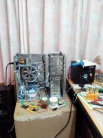
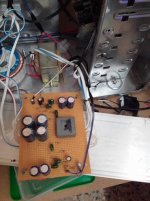
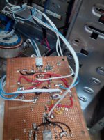
Perhaps if i am constructing the amplifier using stripboard and that is the cause for parasitic impedances? gotta strip it down from the chassis and check everything again ... the IC is mounted below the board lied down onto a heatsink as shown in the picture ... ignore the LEFT module (that is TDA8950 for subwoofer duty) That slim long and wide heatsink is the LM1875 board ...
Attachments
Last edited:
things get stripped off ... back and from out from the chassis ... i didnt see anything amiss or obivious ... what do i need to look out for? The LM1875 is soldered in such a way that it mounts flat against the heatsink ...
Attachments
UPDATE: problem solved ... !!!! 😀😀😀
Thank you Fast Eddie ... you were right that the intermittent hissing problem came from the fine solder debris along the PCB tracks near the inverting and noninverting (pin1 and 2) ... clean them up and now it is running perfect ... thanks ...
It could be a cold solder joint. It could also be parasitic impedances on the board.
Wiggle the parts one at a time and look at the underneath of the board. If a part is loose, you'll see it wiggling on the bottom of the board.
I had an intermittent drop out on a prototype board. Everything looked great but it still happened. I blasted everything with electronics parts cleaner and compressed air. It solved the problem. There was an intermittent parasitic impedance on the board that I couldn't even see with a magnifying glass. I had done some drilling and grinding on the board while it was partially assembled and there was probably fine metal particles lurking.
Thank you Fast Eddie ... you were right that the intermittent hissing problem came from the fine solder debris along the PCB tracks near the inverting and noninverting (pin1 and 2) ... clean them up and now it is running perfect ... thanks ...
This is a typical problem. Glad you sorted it out.
Desoldering braid is a very handy thing to have. A small pick and scraper is handy too. With desoldering braid, you can incorporate surface mount components in your designs, using the "drop and mop" soldering method. You can get "breakout boards" that mount an SMD component and it converts it to (typically) DIP-8 so you can even use a socket. I even put the bypass caps on the breakout board, saving space (and it works better).
Keep building. You'll get better with experience.
BTW Fast Eddie ... for the strip board version of the LM1875 ... is there a more compact way to build this gainclone amplifier? at times i still find that no doubt this is my favourite amplifier module but it takes up way too much space ...
I've seen boards for sale for 1875, 3886, etc. Chipamp.com has them but I heard they're having problems delivering etc.
You could make it a lot smaller on that veroboard too. You can cut and grind the copper strips to suit your layout. In fact, I wouldn't leave long unused strips attached to the input. You're just asking for parasitic interference.
You can make your own board too, and you can buy everything you need from Digikey and even Radio Shack. Digikey has a lot of PCB stencils and if you look you might find one for a TO220-5 package.
Your circuit would probably work better on a small board too. Feedback resistors should be right next to the chip, not way out there. That goes double for bypass capacitors. Layout counts and can have a large effect on circuit performance and operation.
Ya forgot that I used paper caps 100nf for bypass the IC ... could it be the cause of the problem? But other channel tolerate well with it
I can't say if using paper caps for PS bypass duty is causing THAT problem, but I can assure you that having a physically large cap with a lot of parasitic inductance is definitely detrimental to good performance. For PS bypassing you need a physically small (for low inductance) caps with low ESR in those positions (ceramics work well), and they need to be placed as close to the IC's power pins as possible and to a low resistance/inductance 0 volt (common/ground) connection to function properly.
I recommend you visit Tom Christiansen's "Taming the LM3886 Chip Amp" pages - Taming the LM3886 Chip Amplifier - everything Tom writes about the LM3886 also applies to the LM1875 you're using. There's lots of good info there.
Mike
, and they need to be placed as close to the IC's power pins as possible and to a low resistance/inductance 0 volt (common/ground) connection to function properly.
This is very important. I almost always solder these small caps directly to the chip pins on the bottom of the board. A small ceramic capacitor is the right choice for this job.
I'll say it again: layout counts. You don't need a high tech lab to optimize layout. I can do a lot with low tech methods.
- Status
- Not open for further replies.
- Home
- Amplifiers
- Chip Amps
- LM1875 intermittent hissing noise problem


