Hello everyone, thanks for dropping by.
I have read about BPA's for LM3886, and I thought "what about some LM1875?".
It's because I've got a few 1875, caps, and two toroids 12VAC x 5A each.
Therefore, I came up with this circuit (see pdf). According to National's App Note, and LM1875 Datasheet a supply of 12+12VAC would give around 14W into a 4ohm speaker as a single amp and 28W into an 8ohm as a bridged amp. As a bridged amp, the LM1875's can't support less than 8ohm for speakers, this is due to how they "see" load impedance as a bridge (RL/2) each amp. And as 4ohms is the minimum possible load according to its datasheet, an 8ohm load is the min value for them.
Using it as a parallel amp, could give 28W into a 2ohm speaker system.
Then I realized that if I design the amp in order to make it more "versatile" and selectable between two single amps, one parallelled amp or a bridged amp (or using to circuits like that, a full BPA), I could get as many different outputs as I can.
Describing the circuit, this can be achieved by this simple mods:
Two single amps:
Eliminating R2x
Selector must have 2 and 3 bridged (connected by a jumper)
And R10, R11, R12, R22, R23 and R24 can be replaced by wire connection.
Entrada (input in english), is L signal on 1, and R signal on 3 (2 is signal ground).
Bridged Amp:
Eliminating C2b.
Replacing R3b by a wire connection.
Selector must have 2 and 3 connected
And R10, R11, R12, R22, R23 and R24 can be replaced by wire connection.
Entrada (input in english), input channel signal on 1 and 2 is signal ground.
Parallel Amp:
Eliminating C2b and R3b can be replaced by a jumper.
C7b and R8b can be eliminated as well.
Selector must have 1 and 2 jumpered.
R2x can be placed in order to use U1B's output (pin 7) to be connected to another parallel stage (for BPA use), as this signal is inverted from the original input.
And R10, R11, R12, R22, R23 and R24 MUST be present in order to prevent the LM's explode (ha ha ha), because of the offsets output (voltage).
Entrada (input in english), input channel signal on 1 and 2 is signal ground.
for BPA, we need two Parallel config Amps, and (i.e. L channel) pin #3 from Selector of one amp is wired to Entrada's pin#1
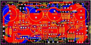
I have created a PCB (attached), and looks good. The thing is that I don't have the money to make this PCB, ha ha... therefore I haven't tried yet, this is an on going project. Maybe if some of you are interested as an investment, get in touch (via PM). Who knows, right?
Anyway, as i said at the beginning, thank you for your time to read my post, I'd like to hear from you, and read your opinions.
Have a nice day!
PS: sorry about my rusty bad english.
I have read about BPA's for LM3886, and I thought "what about some LM1875?".
It's because I've got a few 1875, caps, and two toroids 12VAC x 5A each.
Therefore, I came up with this circuit (see pdf). According to National's App Note, and LM1875 Datasheet a supply of 12+12VAC would give around 14W into a 4ohm speaker as a single amp and 28W into an 8ohm as a bridged amp. As a bridged amp, the LM1875's can't support less than 8ohm for speakers, this is due to how they "see" load impedance as a bridge (RL/2) each amp. And as 4ohms is the minimum possible load according to its datasheet, an 8ohm load is the min value for them.
Using it as a parallel amp, could give 28W into a 2ohm speaker system.
Then I realized that if I design the amp in order to make it more "versatile" and selectable between two single amps, one parallelled amp or a bridged amp (or using to circuits like that, a full BPA), I could get as many different outputs as I can.
Describing the circuit, this can be achieved by this simple mods:
Two single amps:
Eliminating R2x
Selector must have 2 and 3 bridged (connected by a jumper)
And R10, R11, R12, R22, R23 and R24 can be replaced by wire connection.
Entrada (input in english), is L signal on 1, and R signal on 3 (2 is signal ground).
Bridged Amp:
Eliminating C2b.
Replacing R3b by a wire connection.
Selector must have 2 and 3 connected
And R10, R11, R12, R22, R23 and R24 can be replaced by wire connection.
Entrada (input in english), input channel signal on 1 and 2 is signal ground.
Parallel Amp:
Eliminating C2b and R3b can be replaced by a jumper.
C7b and R8b can be eliminated as well.
Selector must have 1 and 2 jumpered.
R2x can be placed in order to use U1B's output (pin 7) to be connected to another parallel stage (for BPA use), as this signal is inverted from the original input.
And R10, R11, R12, R22, R23 and R24 MUST be present in order to prevent the LM's explode (ha ha ha), because of the offsets output (voltage).
Entrada (input in english), input channel signal on 1 and 2 is signal ground.
for BPA, we need two Parallel config Amps, and (i.e. L channel) pin #3 from Selector of one amp is wired to Entrada's pin#1
I have created a PCB (attached), and looks good. The thing is that I don't have the money to make this PCB, ha ha... therefore I haven't tried yet, this is an on going project. Maybe if some of you are interested as an investment, get in touch (via PM). Who knows, right?
Anyway, as i said at the beginning, thank you for your time to read my post, I'd like to hear from you, and read your opinions.
Have a nice day!
PS: sorry about my rusty bad english.
Attachments
You could make the PCB for almost nothing, at home. All you need is some blank 2-sided PCBs and a few supplies that you can buy locally, and a clothes iron (and a laser printer).
My pcb-making webpage is old and no longer shows the correct type of glossy inkjet paper to use. But you can probably find that information in the Homebrew_PCBs group at yahoogroups, or by experimenting. Actually, I think there is a thread on diyaudio about what type of paper to use. Try searching for "toner transfer paper".
My pcb-making page is at Easy PCB (Printed Circuit Board) Fabrication, Using Laser Printer Toner Transfer, with a Household Clothes Iron and Glossy Inkjet Photo Paper; DIY at Home; Better AND Cheaper than Press-n-Peel ( PnP / P-n-P )! Making, Cheap , Economical , fastest fas .
The main thing to beware of is that you won't have plated-through holes. So if there are things that have top-side traces that you won't be able to solder under (e.g. electrolytic caps, IC sockets, et al), that have to connect to the trace on the component side, you have to put a "via" pad or hole, connected on both sides, in some nearby more-accessible location, and solder a wire in it, on both sides of the board.
Last edited:
Thank you so much gootee for your advice. I have done a test, and worked good.
I will follow your advice.
About the BPA, what do you think?
Have you seen the PDF?
I'd like to hear (read) your opinion 🙂
Thank you so much!
I will follow your advice.
About the BPA, what do you think?
Have you seen the PDF?
I'd like to hear (read) your opinion 🙂
Thank you so much!
- Status
- Not open for further replies.