Hi
After a long break from the project I want to push it a bit further toward a finalized design (who am I kidding? - like I would ever really finalize/finish anything..).
Design-goals:
Inspiration:
http://connexelectronic.com/wp-content/uploads/2017/09/SMPS500R.pdf
https://www.st.com/resource/en/datasheet/l6599.pdf
Power inductor tester
Transformer:
Its a massive headache to design and construct the transformer so that it works AND is safe to use.
I know that commercial options are avalible, but: a)Whats the fun in that, b)I could not find one that fits my design-goal.
Please dont even consider building something like this without building a test-rig to verify inductance AND saturation-current (see link above)
Earlier post regarding this project can be found here:
Mosfet failure analysis
Heating in LLC HB mosfets ?
Power limitations for LLC-smps for amplifier
LLC simulation
Heating in LLC transformer
Tests performed to verify design:
Design questions for you all:
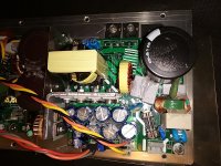
Pictures attached: First prototype on a double-sided PCB and suggested updated design-files.
Disclaimers:
This design is NOT a commercial design for sale. I'm thinking about offering the design-files for free here. My only worry is that a project like this is potentially dangerous and it will require some skill to assemble a safe unit.
You can buy a perfectly good commercial powersupply! This project should never be build if the only motivation is saving money. While the parts are cheap its very labor-intensive to build and test.
After a long break from the project I want to push it a bit further toward a finalized design (who am I kidding? - like I would ever really finalize/finish anything..).
Design-goals:
- Input-voltage: 230Vac+/-10%
- Output-voltage: +/-60V, +/-30V and 12Vdc for a fan
- +/-30V can be configured as regulated or un-regulated.
- Power: enough for a single-channel classD-amp @ +/-70V with 4Ohm Load
- Dimensions: max: 100x100mm pcb
- Standard doublesided 35u PCB
- X-former: ETD34-size core from typical ATX-smps.
- Option for external inductor and split-capacitor for the LLC-tank
- Prim-sec isolation: min 250mils = 6,35mm
- Isolation-distance at HV-side: min 100mils
- Controller: L6599
- Regulation: TL431
- Cooling: minimal airflow. Preferebly no forced cooling for normal operation with 8Ohm load at amplifier
- Disable-input that shuts down the PSU with an isolated 12V input
- Option for external 12V for L6599 in R&D
- Temperature-shutdown if mosfets or transformer gets too hot.
- Designed for amateur hand-soldering.
- All passive SMD are 1206.
- Dissapation in 1206 resistors below 100mW
- Option for over-current-protection: splitcap and/or cap-voltage-sens
Inspiration:
http://connexelectronic.com/wp-content/uploads/2017/09/SMPS500R.pdf
https://www.st.com/resource/en/datasheet/l6599.pdf
Power inductor tester
Transformer:
Its a massive headache to design and construct the transformer so that it works AND is safe to use.
I know that commercial options are avalible, but: a)Whats the fun in that, b)I could not find one that fits my design-goal.
Please dont even consider building something like this without building a test-rig to verify inductance AND saturation-current (see link above)
Earlier post regarding this project can be found here:
Mosfet failure analysis
Heating in LLC HB mosfets ?
Power limitations for LLC-smps for amplifier
LLC simulation
Heating in LLC transformer
Tests performed to verify design:
- Measure hotspots under load and no forced cooling (Xform and mosfets)
- Measure voltage-drop and stability at output with pulse-load of 8ohm from Vcc to GND (roughly 8A at 60V)
- Multiple on/off cycles at mains power with and without load
- Limited noise from speaker with amp and speaker connected to PSU
Design questions for you all:
- Is it OK to have the Ycaps before the CM-coil at the input?
- Do you see any fatal design-flaws?
Pictures attached: First prototype on a double-sided PCB and suggested updated design-files.
Disclaimers:
This design is NOT a commercial design for sale. I'm thinking about offering the design-files for free here. My only worry is that a project like this is potentially dangerous and it will require some skill to assemble a safe unit.
You can buy a perfectly good commercial powersupply! This project should never be build if the only motivation is saving money. While the parts are cheap its very labor-intensive to build and test.
Attachments
Last edited:
SMPS can be lethal and need a lot of care when working on them.
You wont find many off the shelf SMPS transformers as most are custom made to exact parameters. I built my own with parts from RS Components.
The transformer core and frame can be bought in various sizes.
I wound a 17:4 transformer to get 45 volts out.
Once wound I tested it for inductance value and used that with a standard 100nf capacitor to work out SMPS frequencies I needed.
I designed an LLC SMPS using a PIC micro and a IR2113.
I regulated output by applying two different frequencies to the transformer.
1/ Frequency just above resonance for outputting more volts
2/ Much higher frequency when output volts was at regulated voltage.
I also monitored mosfet driver current to decide if there was an overload.
Worked very well.
I regulated output by applying two different frequencies to the transformer.
1/ Frequency just above resonance for outputting more volts
2/ Much higher frequency when output volts was at regulated voltage.
I also monitored mosfet driver current to decide if there was an overload.
Worked very well.
Ok, I had hoped for a little more feedback. - but maybe the title was not catchy enough?
Anyhow, I missed the spreadsheet from member Lorylaci that helped me a lot when I started:
IRS27951 / IRS27952
Anyhow, I missed the spreadsheet from member Lorylaci that helped me a lot when I started:
IRS27951 / IRS27952
Obviously this is not a well known fact. These diodes clamp the resonant tank in case of overload and thus limit circulating current preventing the converter from a resonant catastrophic meltdown of the power MOSFETs. In case of permanent output short these diodes may melt themselves due to excessive current flow. Some cooling may be required. Equipped with these diodes the converter starts flawlessly without a dedicated softstart no matter the size of secondary bulk caps. Works for me like a charm for years now.
Hopefully they are "clamping diodes" as described in this document:
https://www.iosrjournals.org/iosr-jece/papers/Conf.17032-2017/Volume-1/9.%2057-62.pdf
"hopefully" as in: I havnt tested it. Simulation confirms that it works.
Kind reagards TroelsM
https://www.iosrjournals.org/iosr-jece/papers/Conf.17032-2017/Volume-1/9.%2057-62.pdf
"hopefully" as in: I havnt tested it. Simulation confirms that it works.
Kind reagards TroelsM
I picked this idea years ago from the excellent papers written by Bo Yang. I have done the reality-check several times with my 400W LLC output shorted, protected by clamping diodes only. It works!😉Hopefully they are "clamping diodes" as described in this document:
https://www.iosrjournals.org/iosr-jece/papers/Conf.17032-2017/Volume-1/9. 57-62.pdf
"hopefully" as in: I havnt tested it. Simulation confirms that it works.
Kind reagards TroelsM
Besides the simplicity of the clamping diode, I also wanted to include this option, because limiting the voltage over the capacitors means that standard Xcaps can be used and these are easier to find than 1Kv or 2Kv options.
Limiting the voltage also seems to be "safer" option to me? (with regards to creepage-distances at PCB, coil and transformer?
And I have +1000 of the MUR320 on stock 🙂
Kind regards TroelsM
Limiting the voltage also seems to be "safer" option to me? (with regards to creepage-distances at PCB, coil and transformer?
And I have +1000 of the MUR320 on stock 🙂
Kind regards TroelsM
Totally agreed. Clamping prevents from some destructive scenarios. X-caps provide low dielectric loss and are self-healing. The best solution imho.Besides the simplicity of the clamping diode, I also wanted to include this option, because limiting the voltage over the capacitors means that standard Xcaps can be used and these are easier to find than 1Kv or 2Kv options.
Limiting the voltage also seems to be "safer" option to me? (with regards to creepage-distances at PCB, coil and transformer?
And I have +1000 of the MUR320 on stock 🙂
Kind regards TroelsM
Ok, I had hoped for a little more feedback. - but maybe the title was not catchy enough?
Anyhow, I missed the spreadsheet from member Lorylaci that helped me a lot when I started:
IRS27951 / IRS27952
Firstly, Really good attempt please post more on the approach you followed on the magnetics selection, calculation and oh waveforms heavy, light loads.
Would have been good if you added the following for version 2.0
- Independent +5V stand-by power circuit. (look at using a TNY274)
- Isolated shutdown signal command to shutdown the main voltage bus when amplifier experiences problems like Amplifier Output DC offset, Over Current, Over Temperature.
- In combination with R11, consider using a relay based soft start circuit, R11 alone won't last very long and probably explode during an inrush inrush condition. (consider using 3 NTC's in parallel instead of one).
- Lastly, make the SMPS green energy friendly, measure idle power, try and shutdown if no audio is present (using the shutdown command). a good design will probably have 5W at idle.
Last edited:
Hi. Thank you for the constructive criticism. Exactly what I was looking for.
I think the design is pretty green already. Idle heat is very, very low. The controller goes into burst-mode at low power where the duty-cycle for all powerparts are below 10%
Kind regards
I dont understand. What would you use that circuit for?- Should it be fully isolated?Would have been good if you added the following for version 2.0
- Independent +5V stand-by power circuit. (look at using a TNY274)
That option is included. Depending on the configuration the board can be setup to power-down or latched shutdown.- Isolated shutdown signal command to shutdown the main voltage bus when amplifier experiences problems like Amplifier Output DC offset, Over Current, Over Temperature.
I understand the worry, but I´ve seen several commercial design that are build slong the same lines. I cannot find the room for a relay, and a relay would add to the stand-by power. Maybe the NTC in the schematuc is not the correct type? Its not something I have looked into. The prototypes have never blown a NTC.- In combination with R11, consider using a relay based soft start circuit, R11 alone won't last very long and probably explode during an inrush inrush condition. (consider using 3 NTC's in parallel instead of one).
If the PSU should shutdown when no signal is detected I would need a auxiliary PSU to power the detection-circuit. I see the point you are making, but for my design (small "PA") there will always be signal. Lots of signal 🙂- Lastly, make the SMPS green energy friendly, measure idle power, try and shutdown if no audio is present (using the shutdown command). a good design will probably have 5W at idle.
I think the design is pretty green already. Idle heat is very, very low. The controller goes into burst-mode at low power where the duty-cycle for all powerparts are below 10%
Kind regards
Hi. Thank you for the constructive criticism. Exactly what I was looking for.
I don't understand. What would you use that circuit for?- Should it be fully isolated?
Kind regards
The 5+V standby circuit in question is isolated (with its own small transformer) and acts as an "always ON active" +5V to used to supply external electronics like a microcontroller supervisory circuit. Think about it? The main supply needs some active voltage to enable/disabled it externally, obviously the turn./off is still via an optocoupler.
https://www.power.com/sites/default/files/product-docs/tny274-280.pdf
74001 | 1 Output 4.5 → 6W Flyback SMPS Transformer, 85 → 265V ac, 3.3 → 6V ac | RS Components
https://www.onsemi.com/pub/Collateral/NCP1070-D.PDF
I see you using ancient Q1/Q2 IRFP240 transistors with a modern resonant controller, is there a reason for this ?
Fairchild/On-Semi has some better modern offerings you may want to look at.
For this kind of PSU I dont see the point in using an extra small transformer. Maybe for an application where most of the time would "standby", but I dont need that.
I have been thinking about ways to make this a DIY-friendly project and thus its better to make one transformer than 2.
The transistors dont appear to very critical in this application. I'm testing with old IRFP450 and these work fine. I seem to remember that one of the benefits of resonant LLC is that the switching becomes less critical because of the ZVS.
Firstly, Really good attempt please post more on the approach you followed on the magnetics selection, calculation and oh waveforms heavy, light loads.
As far as "selection" goes: I wanted to use the TX-core from a typical ATX-PSU because they can be found everywhere. Its probably not very good for this purpose, because the cross-section is only 1cm2, but often they are free🙂
The magnetics was a major headache to begin with. Mostly because I tried to implement both Lr and Lm on the re-purposed ATX-core. I could not get the ratio higher than 1:3 and its hard to control the parameters.
A much better path is to wind the transformer with pri and sec covering the whole core and aiming for a ratio from 1:10 to 1:20. Number of windings can be found with one of the calculators online. Then the gap-size can be verified with a coil-tester that can drive the core into saturation. Saturation must occur at a current above the max primary current.
Theoretical currents can be found with simple models in LtSpice.
In some of my later prototypes i had way too much heat in TX and mosfets because the circulating currents was 12A and the TX saturated at 8A.
When the TX is wound and tested, the remaining inductance can be wound on a separate torroid in series with the primary. I used a red core like the ones used for classD output-filters. Again: verify saturation-current.
REMEMBER: TX must be wound with respect for safety. Used a heat-resistant tape and wound 5 layers between pri and sec. Implement appropriate creepage-distance, -including the area around the TX-terminals.
Last edited:
your calculation approach looks questionable to me. Primary saturation current describes the magnetizing current capability but not the reflected primary current it is designed for. In an LLC the xformer is voltage driven and you have to consider the primary Vsec product not saturating the core. The gap does not help here, theoretically the LLC may work without any gap. Practically I insert a gap that increases primary circulating magnetizing current upto a level that it can charge the output capacitance to the opposite voltage rail lossless during deadtime.
your calculation approach looks questionable to me. Primary saturation current describes the magnetizing current capability but not the reflected primary current it is designed for. In an LLC the xformer is voltage driven and you have to consider the primary Vsec product not saturating the core. The gap does not help here, theoretically the LLC may work without any gap. Practically I insert a gap that increases primary circulating magnetizing current upto a level that it can charge the output capacitance to the opposite voltage rail lossless during deadtime.
I would not say that I have a calculation approach. - that way beyond me 🙂. I followed a few of the spread-sheets thats available online and they gave similar results.
With my limited understanding, i theorized that the core was going into saturation and tried increasing the gap. It helped.
The prototype can regulate the Vout over a fairly large Vin-span, the heating is not excessive and ZVS-switching is maintained over most of the range, so I'm happy. That being said, I could probably do more measurments to verify that the design is operating as intended
Kind regards TroelsM
For this kind of PSU I dont see the point in using an extra small transformer. Maybe for an application where most of the time would "standby", but I dont need that.
Simple question then, if the amplifier circuit detects a fault and disables the SMPS controller to command the power supplly to power down to 0V, then what voltage will be used to command the disabled voltage to turn on (take into account no voltage is present), its actually less a standby question but the availability of a independent active rail.
Anyway, I think this is important and basing your design other cost optimized planned obsolescence designs is not a good way to select design criteria.
My logic (maybe flawed) is that a fault that is serious enough to command a shutdown, should also provoke a power-cycle from the user.
So in the event of a fault, the stored energy in the caps are used to disable the PSU. That's a latched operation and requires user interaction to reset
Makes sense?
So in the event of a fault, the stored energy in the caps are used to disable the PSU. That's a latched operation and requires user interaction to reset
Makes sense?
- Home
- Amplifiers
- Power Supplies
- LLC design review