Replace the diodes. 10A T was way too high. An unforgivable user error. A home installation normally has 16A B curve breakers but please calculate with the 10A.
P = U x I
That was about the power your device consumed when you switched it on. Not difficult to answer but I have to do something now.
Next time use “light fusing”. Better one fuse spent too much than a device wrecked.
P = U x I
That was about the power your device consumed when you switched it on. Not difficult to answer but I have to do something now.
Next time use “light fusing”. Better one fuse spent too much than a device wrecked.
Last edited:

Alright so to make things clear I need to:
- Replace FCU20A40 diodes and 6C should be a fine replacement for previous 8C diodes
- Replace amplifier boards using thermal pads
- Install 4A inline fuses between power supply and amp
- Install a lower mains fuse
- Test power supply with new diodes
- Test one amplifier module at a time with dim bulb tester connected
- Connect speaker protection
- Check DC offset and adjust
After I’ve done all these steps I’m ready to connect the amp to my speakers? Are there any more things I’m missing?
I would at least go through some basic load torture tests into dummy loads at all power levels, including clipping, before hooking up speakers.
I would test the output MOSFETs as well. De-solder them and test with a meter.
If you are unsure of the health of the MOSFETs, consider replacing them all. They are not that expensive.
https://www.digikey.com/en/products/detail/vishay-siliconix/IRFP9240PBF/811573
https://www.digikey.com/en/products/detail/vishay-siliconix/IRFP240PBF/811552A
Good luck! 😊
If you are unsure of the health of the MOSFETs, consider replacing them all. They are not that expensive.
https://www.digikey.com/en/products/detail/vishay-siliconix/IRFP9240PBF/811573
https://www.digikey.com/en/products/detail/vishay-siliconix/IRFP240PBF/811552A
Good luck! 😊
Hi again, I was wondering if the diodes for the rectifier have to be matched? As in should I buy an extra number of diodes to try and get similar ones or is it ok just to buy 4
For your (and everybody else in your household) safety..... This is not a guessing game.Alright so to make things clear I need to:
- Replace FCU20A40 diodes and 6C should be a fine replacement for previous 8C diodes
- Replace amplifier boards using thermal pads
- Install 4A inline fuses between power supply and amp
- Install a lower mains fuse
- Test power supply with new diodes
- Test one amplifier module at a time with dim bulb tester connected
- Connect speaker protection
- Check DC offset and adjust
After I’ve done all these steps I’m ready to connect the amp to my speakers? Are there any more things I’m missing?
What is the VA (watt) rating of your power transformer??
It´s absolutely imperal, that the fuse NEVER exceeds the transformers power rating.
Just buy 4 pcs.Hi again, I was wondering if the diodes for the rectifier have to be matched? As in should I buy an extra number of diodes to try and get similar ones or is it ok just to buy 4
The transformer is rated for 300VAFor your (and everybody else in your household) safety..... This is not a guessing game.
What is the VA (watt) rating of your power transformer??
It´s absolutely imperal, that the fuse NEVER exceeds the transformers power rating.
Alright thanks I’ll use 1.6A for mains fuse but someone earlier was saying to use 4A fuse between power supply and amplifier but then that doesn’t make sense in this case right? Should I just use 1.6A everywhere?
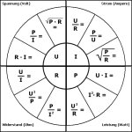
Yes..... Learn that "circle" in #51.Alright thanks I’ll use 1.6A for mains fuse but someone earlier was saying to use 4A fuse between power supply and amplifier but then that doesn’t make sense in this case right? Should I just use 1.6A everywhere?
To give you a little hint:
If 230 volts delivers 230 watt, that equals 1 Amp. current draw (primary)
If 23 volt delivers 230 watt, that equals 10 Amp. current draw (secondary)
Cut out in cardboard: If your secondary draws 230 watt, you need (at least) 1 Amp fuse on primary and 10 Amp fuse on secondary, cappice??
Now you see, why you need bigger fuses on the secondary side???
But heat sink burrs cutting through them will do it for sure
I recently finished debugging a build where this was the cause of a problem. I had a short between the middle pin of a MOSFET and the chassis. I assumed the MOSFET was shorted. I took out the board to replace it and tested the surrounding components...to find out the short had gone away.
Put the board back in, and the short returned.
Long story short...took me a while to realize I forgot to deburr the hole I drilled for the MOSFET. The burr was tiny but sharp and pierced through the silpat insulator ever so slightly.
Life.
So then because the power supply delivers +-55V and the amplifier is supposed to deliver a maximum of 150W then I should in theory use 2.7A fuses?Yes..... Learn that "circle" in #51.
To give you a little hint:
If 230 volts delivers 230 watt, that equals 1 Amp. current draw (primary)
If 23 volt delivers 230 watt, that equals 10 Amp. current draw (secondary)
Cut out in cardboard: If your secondary draws 230 watt, you need (at least) 1 Amp fuse on primary and 10 Amp fuse on secondary, cappice??
Now you see, why you need bigger fuses on the secondary side???
It is a little more complex than that but indeed works like that at the primary side with just 1 voltage. Don't make this new territory directly too difficult 🙂
Since I had amplifiers that had too light DC fuses and saw what happened when of course just 1 blew I would not use fuses there. Can you imagine what happens if just 1 blows?
Just use the 230V 1.6A T one. Keep it simple and adequate but check your work by measuring continuity between transistors and heatsink. Use an LBT. Show it to the people here or an experienced friend before thinking of switching it on.
Last edited:
No.So then because the power supply delivers +-55V and the amplifier is supposed to deliver a maximum of 150W then I should in theory use 2.7A fuses?
Your calc. is wrong.
150 watt from 110 volts (2 x 55) is 1,363636363636364 = 1,6A (and then in the old days, you´d add a little extra for charge-surge
of the capacitor bank.
but as Jean-Paul already explained (and that´s really good advice): Drop the secondary fuses and settle for the mains one.
What happens to your speakers, if only one of the secondary breaks down is, that the speaker get´s 55 volt DC across the
terminals. That will burn the voice coil ASAP. If for some reason the amp breaks down/shorts, the correct sized mains fuse will blow anyway 😉
Far better solution from secondary fuses would be a speaker relay circuit with DC-detection.
Last edited:
If you are using a primary fuse it would end up needing to be in the 3 amp range. 1.6A doesn’t take efficiency and power factor into account. An amp and a half would be good for light loading and typical use, but when the party gets going expect nuisance blowing.
If you blow mains fuses on startup (due to hungry caps or core saturation) then a soft start circuit is needed. Or oversize the fuse, and live with the consequences of that. Time delay fuses work too, but those solutions offer less protection for the circuitry. They will prevent fires, but not necessarily blown output transistors.
If you blow mains fuses on startup (due to hungry caps or core saturation) then a soft start circuit is needed. Or oversize the fuse, and live with the consequences of that. Time delay fuses work too, but those solutions offer less protection for the circuitry. They will prevent fires, but not necessarily blown output transistors.
As the old saying goes "the transistors are there to protect the fuse!"😊
If we turn that on its head, what we really want is the fuses to protect the output MOSFETs. Looking at the data sheet here: https://www.vishay.com/docs/91210/irfp240.pdf
We see that @ 55V each MOSFET is capable of delivering roughly 5A. So, 3 MOSFETs in parallel is 15A. At 55V per rail, that is U=R*I or R = U/I meaning that 55V/15A = 3.7 ohms. But remember this is steady state, DC. If you cranked 15A into 3.7 ohm at 55V, you get P=U*I or 820 Watts DC into your speaker. Not good. Music is however dynamic. Not DC. So, we want a fuse that protects the MOSFET and speakers from severe damage. At 3A or 4A we are much more conservative. 4A in 4ohm is only a DC of 16V. And 16V at 4A = 64W. When you have 64W DC on your speaker, that is causing a fair amout of heat in the voice coil. Many drivers will not survive - as they are designed for frequency modulated AC.
Many on this forum knows the Dick Oshler axiom that "only the 1st watt matters".
At 1W in 4ohms we are drawing around 650mA... So, this focus on max current draw is optimizing for the wrong end of the scale.
Better to run a MOSFET output stage in class A at low volumes (say less than 1A idle) and the protect speakers and MOSFETs with a somewhat conservative fuse in case your cousin cranks the amp while drunk at your next party. 🍺🍻
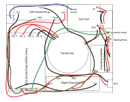
First post. At the right in the middle:
The layout could have been more optimal (transformer at the front, no AC wiring crossing with input/output wiring etc) but case size probably forced this.
The layout could have been more optimal (transformer at the front, no AC wiring crossing with input/output wiring etc) but case size probably forced this.
Attachments
Last edited:
- Home
- Amplifiers
- Solid State
- LJM L15 Exploded