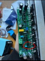
Hello, today I built my first DIY amp with an LJM L15 and when I switched it on it exploded, this came as a surprise as I had made sure that the output voltage from my power supply was ±55 V I had also triple-checked my wiring to make sure that I wasn't plugging the VCC and VEE in wrong. I am planning to buy a new pair of L15s to retry this build, but I want to know what went wrong. I've attached a coupling schematic and pictures of which transistor blew on one channel and where the PCB burned out on the other.

Attachments

Oh dear, that's not good. We would need to see a proper circuit of the amp really although if its a ready built module it should of course be tested and working.
Please please please... if you try again use a DBT (dim bulb tester). You may need to bypass the soft start (circuit dependent) to use the bulb. Also power up one channel at a time when testing.
Please please please... if you try again use a DBT (dim bulb tester). You may need to bypass the soft start (circuit dependent) to use the bulb. Also power up one channel at a time when testing.
The left channel signal in is connected to the left rca jack (supposed to be two cables in the diagram but I must have forgotten). But when this happened, there was no input connected so it was basically not connected to anything
The module came from audiphonics and they say that they test all there modules before selling them. I have also contacted them to see if they could help.
You can buy a variac. A DBT has to be cobbled together, and their use isn’t officially sanctioned. But they usually WORK to prevent exactly what happened. A DBT does not always prevent damage if something is amiss, but it will prevent you from being hit by flying pieces of transistor.
You build one. It is just a mains filament bulb (such as 60 watt GLS type) in series with the mains supply. They work well in practice and prevent large current flows.Can you buy a dim bulb tester or do you have to build one yourself?
Scroll down post #30 here for quick explanation of how they work:
https://www.diyaudio.com/community/threads/quad-303-repair.425457/post-7971026

Building an amplifier isn't easy or straightforward. It requires a lot of experience and minimal electronics knowledge. All of this is mandatory even if you're building a third-party design and they tell you it's proven.
My advice when building an amplifier is to follow these basic steps:
1. Assemble, connect, and test only the power supply, in a vacuum.
2. Assemble, connect, and test a single channel connected to the power supply already tested in the previous step, installing test fuses on the 500mA power rails. No amplifier channel should ever reach that power consumption with the bias potentiometer at minimum. Therefore, if the fuses blow during the test, you'll need to check that channel, and you'll need more in-depth electronics knowledge.
3. Do the same with the other channel.
4. Connect and test the speaker protector.
5. When all of these elements have worked properly, both separately and individually. You start connecting everything together.
6. At this point, you'll need to check the cable connections several times.
7. The final step is to connect and test the amplifier with the bulb in the power cable as a final test.
If everything went well or the issues were resolved, it's time to enjoy the music.
I just found that there is continuity between some of the legs of the transistors and the heat sinks. This must be the issue right? Now just to understand why this is the case. There’s continuity on a total of 5 transistors (3 on the right and 2 on the left). The continuity is only on the middle leg of the transistors. Could it be that some metal has poked through the transistor from the heat sinks when screwed on? Are there any other theories?
Perhaps it is just me - and my older eyes - but where is the mica/silicon insulators between the heatsinks and the power MOSFETs?
Looking at your pictures, I cannot see any insulation...
If you are new at this hobby, this may have been an oversight.
Also: your diagram does not show fuses between then power supply and the rails for each amp module. Strongly advise to have 4A fuse (4 in all) between the power supply rails and the amp modules.
Sounds like the insulators were omitted entirely. But heat sink burrs cutting through them will do it for sure. It’s even more insidious - it might wait till it’s hot before it actually shorts on you. After you’ve taken it off the dim bulb…..
🙂 vilfort posted before me. What kind of compound are you using between the heatsink and the device?
If the drawing is the same as the real board then you made the wrong connection .
The positive power connection is on the left and not on the right side .
The positive power connection is on the left and not on the right side .
I used thermal grease between the transistors and the heat sink. I had read that thermal grease works better than thermal pads thus didn’t think they were necessary.
The drawing is incorrect (I made the drawing before I had revived the amp) the way I actually connected it was correct.
The drawing is incorrect (I made the drawing before I had revived the amp) the way I actually connected it was correct.
Is this always the case because I have seen videos of people only using thermal grease? Thanks for the help
I don't know if this is the case here, but If I remember correctly, some thermal compounds for computer CPU's are conductive, and shouldn't be used for mounting transistors. The proper grease with a mica pad or a silicone pad with out grease should be used.
- Home
- Amplifiers
- Solid State
- LJM L15 Exploded