The elephant in the room.
I am a mechanical kind of guy. I think in terms of pressure, pumps, control valves and horsepower. A lot of what has been said in this thread does not square with me.
I finally broke down and purchased. The AES paper “Noise in Triodes…”, so far a few things have reached out and grabbed my attention.
Every triode, each and every valve tested was tested at a B+ voltage of 150 volts, no exception.
The cathode resistor value was the control variable used to adjust the cathode current while B+ voltage was held constant.
Equation 3 includes an empirical constant “c” used as an exponent. The value 2 was used throughout the remainder of the paper for “c”. This statement was used in regard to “c”, “the flicker noise is proportional to the power dissipation in the device”.
Section 5.1 states “… flicker noise current is directly proportional to mean anode current…”
This is my added observation, if cathode current is held constant; flicker noise will be proportional to plate voltage. If cathode current is held constant and the plate voltage is reduced to 50 volts the flicker noise will be reduced to 1/3 of what it was at 150 volts. As the plate voltage is reduced to 50 volts the required cathode resistor value will reduce in value perhaps by half and in the process change the shape of the grid voltage “hockey stick” reducing the rp, gm and reducing the shot noise in the process. All desirable things for the first stage of an amplifier with a small input voltage.
DT
Hi DT,
I think there may be a flaw in your logic, or you may have over-interpreted what Merlin said in his paper.
According to Eq 3 in Merlin’s paper, flicker noise depends on bias current, and is (very) approximately proportional to the square of the bias current.
Device power dissipation also depends on the square of the bias current, or on the product of current and voltage.
But that does not mean that flicker noise necessarily depends on voltage or device power dissipation.
Best,
Scott
Hi DT,
I think there may be a flaw in your logic, or you may have over-interpreted what Merlin said in his paper.
According to Eq 3 in Merlin’s paper, flicker noise depends on bias current, and is (very) approximately proportional to the square of the bias current.
Device power dissipation also depends on the square of the bias current, or on the product of current and voltage.
But that does not mean that flicker noise necessarily depends on voltage or device power dissipation.
Best,
Scott
Hello TavishDad,
Thank you for the dialog.
It is not my logic or my logic interpretation. This quote is copied from the paragraph immediately below Equation (3), “…the flicker noise power is proportional to the power
dissipation in the device.”
As to 1/f noise being very “approximately proportional” to the square of the bias current; Equation (7) uses the I^2 term to calculate EIN. This is what the paper includes, not my interpretation.
If indeed the 1/f noise is proportional to the power dissipation in the device; either current, voltage or both can vary the power dissipation in the device.
Looks to me that more testing is needed with at least a second plate voltage perhaps several plate voltages to plot some data points to see if things are linear or follow some kind of curve.
I just received a shoebox full of 6AK5’s, this valve has a reputation of following the RF rule of thumb “2.5/gm” concerning Shot Noise. I will send you 3 or 4 for testing at varying plate voltage and constant current.
DT
Hi DT,
I agree with you. On one hand, flicker noise is very widely studied, and I’ve never seen any measurement or theory to suggest that it has a significant voltage dependence (flicker noise is mainly a function of device current). But almost all the data out there is on transistors, there is very little recent or reliable measurement data of any kind on vacuum tubes, except for Merlin’s paper. So to be thorough, I’ll check how measured noise varies with the plate voltage for a couple types of tubes.
I’ll have to think about the right way to do this experiment – it probably requires a couple of test circuits with the same plate current but different plate voltages.
Keep in mind that there is large sample-to-sample variation in tube noise, and that even the change in input-referred noise with cathode current tends to be over-shadowed by the tube-to-tube variability.
My to-do list on this project is getting very long, so it will be at least a few weeks……….
Scott
Hi Everyone,
I updated the measurement list on my website to include additional samples of the JJ E88CC, Electro-Harmonix 6922, and Tung Sol Reissue 6SL7GT.
Downloads – Tavish Design
Unfortunately, 4 of the 6 new samples of JJ E88CC were quite noisy, and I did not include their measurements in the tabulated average or sample standard deviation (if I had, it would have raised the average NF by 8dB!). I noted the “discarded” tubes in column 3 of the table. The 6 samples came from three different vendors, so it is not a vendor-related issue. All three vendors cheerfully agreed to exchange the noisy tubes, so I’ll measure their replacements in a couple of weeks. Hopefully, these noisy samples are just a random event.
The Tung Sol Reissue 6SL7GT is very expensive, and the samples are not particularly low noise, but the samples I have measured do seem fairly consistent.
Scott
Hi DT,
I agree with you. On one hand, flicker noise is very widely studied, and I’ve never seen any measurement or theory to suggest that it has a significant voltage dependence (flicker noise is mainly a function of device current). But almost all the data out there is on transistors, there is very little recent or reliable measurement data of any kind on vacuum tubes, except for Merlin’s paper. So to be thorough, I’ll check how measured noise varies with the plate voltage for a couple types of tubes.
I’ll have to think about the right way to do this experiment – it probably requires a couple of test circuits with the same plate current but different plate voltages.
Keep in mind that there is large sample-to-sample variation in tube noise, and that even the change in input-referred noise with cathode current tends to be over-shadowed by the tube-to-tube variability.
My to-do list on this project is getting very long, so it will be at least a few weeks……….
Scott
Scott
I live in California; we are experiencing a severe drought. A vendor came by the office and handed out a few 1.5 gallon per minute shower heads. I installed one of the things in my home. After standing in the shower my wife came down stairs and asked, “What happened to the water pressure in the shower”? This little story points out a few things; how we think and talk about stuff, pressure, flow rates and included inline flow restrictors.
Experiencing the reduced flow rate in the shower my wife thought of it as a pressure problem. In the electrical realm we speak of AC and DC, Alternating Current and Direct Current not Alternating or Direct Voltage.
The poster child of flicker noise is resistor excess noise. The flicker noise is proportional to the current. In the discussion we neglect the relationship between voltage and current. For each incremental delta in current there is also an corresponding incremental delta in voltage. This is a power relationship as in P=EI, P=V^2/R or I^2*R.
Back to the shower;
With the original shower head and the valve on the shower wall shutoff the original pressure is 50 PSI and the flow is 0 gpm. If I slightly open the valve on the wall the flow goes to some value say 1 gpm. If I open the valve on the wall an additional increment the flow increases to 2 gpm. With the wall valve fully open the supply pressure is unchanged and the flow rate is 3.5 gpm.
Now I change the shower head to the new one with the added flow restrictor;
With the wall valve in the shutoff position we still have the original pressure of 50 PSI and 0 gpm flow. Now we increment through the intermediate position to full open. At full open there is 1.5 gpm, same 50 psi and same wall valve. The added inline resistance to flow is the only thing that has changed. In the mechanical world the wall valve is said to have reduced authority.
In the mechanical model we use the term control valve authority. In the electrical model the equivalent term is transcoductance or gm.
The moral of the story Scott is this; in your noise test circuits an added anode resistor does change the test circuit transconductance to the tune of u/(rp of the tube+ the anode resistor). It is the circuit under test not the DUT that you are measuring.
If you will notice in your test results that the reported tube noise consistently goes down as the anode resistor in the test jig goes down in value.
DT
Attachments
On one hand, flicker noise is very widely studied, and I’ve never seen any measurement or theory to suggest that it has a significant voltage dependence (flicker noise is mainly a function of device current). But almost all the data out there is on transistors, there is very little recent or reliable measurement data of any kind on vacuum tubes, except for Merlin’s paper.
If you are interested in the physics and the trends, read (chapter 8 of) Aldert van der Ziel's 1954 book Noise. It isn't recent, but then again, valve construction hasn't changed that much over the past six decades. If you are interested in the actual values for common production valves, you won't find it in there, though.
Last edited:
Hi DT,
Sorry, I can’t agree with you about that one. The test fixtures are designed so that the plate load resistor contributes negligible noise, as we’ve discussed before in this forum.
For example, consider the Shuguang 12AX7B, with 100kΩ plate load resistor, average gain of 61.0, and average input-referred noise of 0.588 µV rms.
Thermal noise across the plate load resistor in an 8 kHz BW is En = SQRT(4kTRf) = 3.64 µV rms.
Referred to the input of the tube, that noise is 3.64/61.0 = 0.0597 µV rms.
The average total input-referred noise is 0.588 µV rms. When adding, subtracting, or comparing noise, we must use noise powers, since random noise is incoherent.
So the fraction of noise contributed by the plate load resistor is (0.0597^2)/(0.588^2) = 0.01, or about 1%.
Scott
Hello Scott,
In regard to the added thermal noise of the included anode resistor you may be completely on target. I am not addressing the resistor thermal noise.
The point that I attempted to make is that the added anode resistor effectively reduces the transconductance / gm of the tube. Additional noise comes from lowering the effective gm of the tube.
We should discuss the excess noise or flicker noise from the resistors. In your photo of the test jig I do not see any metal foil or metal film resistors. What I do see is carbon film and metal oxide resistors. With 150K and 100K resistors there are large DC potentials across these anode resistors. This makes for potentially significant levels of excess or 1/f noise, particularly at higher ma currents.
DT
I probably shouldn't have worded it like that. Flicker noise is indeed dependent on cathode current, not the anode-cathode voltage (which is clear from the fact voltage does not appear in eqn (3) ). It is more of a casual obsevation that mean-square flicker noise current is roughly proportional to the square of cathode current, and we all know that 'current squared' is proportional to power; the old "I squared R" mantra. In most devices, noise is in some way proporitonal to current, and dissipation is also propotional to current, therefore noise and dissipation are often proportional to each other, even though they are not causally related (at least not significantly). I probably shouldn't have mentioned it! 🙄This quote is copied from the paragraph immediately below Equation (3), …the flicker noise power is proportional to the power dissipation in the device.”
The anode resistor does not affect the intrinsic transconductance of the tube, it only alters the available voltage gain. Some people call this the 'apparent' transconductance, but that is only a mathematical short hand. With a given mean anode current, the noise current generated in the tube (and therefore also the EIN and noise factor) remain the same whatever you do with the anode resistor. This does not include the effects of grid current noise, of course, but that is usually negligible.The point that I attempted to make is that the added anode resistor effectively reduces the transconductance / gm of the tube. Additional noise comes from lowering the effective gm of the tube.
This too is usually negligible for anything other than carbon comps. You have to be pretty ignorant or unluky to build a triode gain stage where anode resistor excess noise manages to exceed valve noise.We should discuss the excess noise or flicker noise from the resistors.
Test Results Please!
Merlin,
I believe you may have had it correct the first time.
For Formula (3)
K = An empirical constant particular to the device.
I will start where we may have some agreement.
Given:
E=I*R
Watts = P = E*I = I^2*R = E^2/R
For Formulas (6) and (7) the Flicker noise term is dressed up as K*I^2. K looks like a resistor dressed up in a constants’ clothing to me. K*I^2 shure looks a lot like I^2*R and I^2*R looks a lot like a watt to me. As I said, you may have had it correct the first time. (There may also be some addition device particular things included in the constant K.) Test results?
The anode resistor does affect the transconductance of the circuit under test. Change the grid voltage and the circuit current does not change as much as the valve alone without the added anode resistor. Tell us what difference it makes if the plate resister in series with the plate resistance is inside the vacuum of the envelope or not. Better still show us with test results. Scoffing has no weight. Test results?
Noise wise, are you telling us that using carbon film and metal oxide resistors only has a negligible benefit over using metal film or metal foil resistors? If so many of us have been wasting our money? Test results?
Where did “pretty ignorant or unluky”, come from?
DT
@DT
You need to take care not to over generalise. For example your point about changing the anode resistor changing transconductance. If you change only the anode resistor, then the operating point changes and the current changes. As gm depends if current then gm changes. However, if you change the anode resistor and then change the cathode resistor so the current remains the same, then gm will be unchanged.
The same applies to your point about the relationship between flicker noise and power dissipation. If you change the operating current and keep the plate voltage unchanged then the tube dissipation is directly proportional the current squared. However, if instead you change the anode resistor, the current changes but so does plate voltage so the tube dissipation is no longer directly proportional to the current.
The point of all this is that as far as flicker noise is concerned, it is the tube current that matters and not the operating point at which that current occurs.
Cheers
Ian
Show us the test data.
Hello Ian,
Not so much over generalization as being too easy with assumptions that are not documented to be true by the benefit of test data. You and I are not the ones posting test reports or publishing AES papers.
Your statement “…then gm will be unchanged”, is not true for at least a couple of seasons. Keeping in mind that u remains fairly constant, gm=u/rp and that rp is equal to the slope of the line tangent to the plate curve at the operating point.
1. For a D3a valve the rp at an operating point of 245 volts anode, 8ma and grid voltage of -2.75 is significantly different than the rp at an operating point of 50 volts anode, 8ms, and a grid voltage of -0.5.
2. This second example has a few more details. For the same D3a valve let’s select an operating point more in the middle, 130 volts anode, 8ma, and a grid voltage of -1.5 volts. Now we pick a B+ voltage of 301.5 volts and an added 21.25K ohm anode resistor. At the given 8ma current the voltage drop across the resistor is 170 volts. Now we change the grid voltage to -0.5, assuming for the moment that the anode voltage remains 130 volts we would expect the current to increase up to nearly 48ma, this cannot happen. With the change in grid voltage the current will increase, and so will the voltage drop across the anode resistor. With the increase in current the plate voltage will drop from the orginial 130 volts. All this adds up to a significantly less current increase than would be expected from the grid voltage change and reported gm of a D3a valve. In this case the gm of the valve remains largely unchanged. It is the equivalent gm of the test circuit that results in the less than expected current change due grid voltage and valve gm alone. (Remember the shower valve analogy.)
My wife says that food is on the table. Flicker discussion will come later.
Short version for now.
Show us the test data.
DT
Hello Ian,
Not so much over generalization as being too easy with assumptions that are not documented to be true by the benefit of test data. You and I are not the ones posting test reports or publishing AES papers.
Your statement “…then gm will be unchanged”, is not true for at least a couple of seasons. Keeping in mind that u remains fairly constant, gm=u/rp and that rp is equal to the slope of the line tangent to the plate curve at the operating point.
I think you are missing the point and perhaps I badly expressed it. Flicker noise is definitely proportional to plate current squared. If you change the plate resistor, you change the operating point. If that means the current changes then the flicker noise will change. If you change other components such that the current remains the same then the flicker noise will be unchanged.
Cheers
Ian
Hello Ian,
I reread your previous post and today's post several times; I see where we may be talking past each other.
There are two types of noise that fill the old musty books, beginning in the 1920’s; Shot Noise and Flicker noise, Flicker Effect as it was called then.
The old books say that Shot Noise is independent of current.
The early RF designers found a relationship between Transconductance (gm) and Shot Noise. You previously posted that relationship as Shot Noise being a function of 2.5/gm. Some valves follow this rule better than others. The 2.5/gm rule is silent regarding the Flicker Effect.
My discussion of gm and the effect of adding an anode resistor only address shot noise.
I would like to see noise test results showing the effect of changing B+ voltage and anode resistor value while holding current and the operating point of the valve constant.
Let’s look at flicker noise another day.
DT
I do not think the old books say shot noise is independent of current. They do derive the 2.5/gm rule and of course gm is directly related to idle current ( I think one is the log of the other but I forget which way round). This is why the low noise audio design pundits tend to recommend using high gm tubes at high currents for lowest noise. Unfortunately all this does is minimise shot noise and takes no account of the optimum operating conditions for flicker noise.
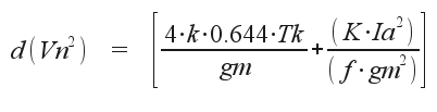
The problem is, shot noise decreases as current increases but flicker noise increases as current increases. At some current there is a noise minimum and I think that is what the curves in Merlin’s paper are intended to show.
On my PC desk top I permanently have an image of the formula for triode spot noise:
Cheers
Ian
Attachments
I would like to see noise test results showing the effect of changing B+ voltage and anode resistor value while holding current and the operating point of the valve constant. DT
If you keep the operating point of the valve constant and if your anode resistor has negligible 1/f noise, you can straightforwardly calculate what impact simultaneously increasing the supply voltage and the anode resistor value have.
Imagine you AC short-circuit the output, that is, you connect it to some sensitive AC current meter through a large coupling capacitor. All noise current from the valve will then flow into the meter, as will the noise current of the anode resistor, which has an RMS value of sqrt(4kT*delta_f/Ranode) over a bandwidth delta_f.
Hence, the noise current flowing into the meter gets worse with reduced Ranode. The contribution from the valve stays constant, but the resistor itself contributes more as Ranode is reduced.
What we are usually interested in, is the equivalent input noise. Except when the source impedance is extremely high or the grid is driven into conduction, the low-frequency input noise is almost completely equivalent input voltage noise. By definition, this is the amount of noise voltage you have to put at the input of a hypothetical noiseless valve to get the same amount of noise at the output as you get with the actual valve. Hence, this is simply the output noise current divided by the voltage-to-current gain of the amplifying stage. With the output AC shorted, that gain is simply the gm of the valve (assuming a common-cathode stage with decoupled cathode resistor).
Hence, the equivalent input noise voltage increases with decreasing Ranode. The contribution of the valve stays constant as long as the valve's operating point is kept constant, but the contribution of the anode resistor gets worse.
Things would get slightly more complicated if you would for whatever reason be interested in the open-circuit output noise voltage, rather than the equivalent input noise. You can calculate the output voltage noise by applying a Norton-Thévenin transform on the output, that is, by multiplying the short-circuit noise current at the output with the output impedance. For low frequencies, the output impedance of the amplifying stage is the parallel value of the valve's internal resistance and Ranode (assuming a common-cathode stage with decoupled cathode resistor). This obviously goes to zero for Ranode approaching zero, but this is of little practical use because then there is no signal coming out anymore either.
Last edited:
Hello Ian,
Yes the noise of a triode is the RMS sum of Shot Noise and Flicker Noise.
Assuming that Anode voltage is held constant and there is no added anode resistor, shot noise goes down as current goes up. Flicker Noise goes up as current goes up. As a result there is a happy place, a current, where total noise is at a minimum. These are the conditions Merlin used to test valves for his paper.
I suggest that Merlin go back to the bench;
3 test conditions, no anode resistor
1. Low anode voltage and a wide range of currents.
2. Mid anode voltage and a wide range of currents. (this should be the original test conditions)
3. Hi anode voltage and a range of wide currents.
After this series of tests answer these questions, is there a happy place, a current, where total noise is at a minimum? Is it the same happy place, for each of the 3 test voltages, a current, where total noise is at a minimum?
I would like to see an additional noise test showing the effect of changing B+ voltage and anode resistor value while holding current and the operating point of the valve constant. This testing would show the noise effect of a plate resistor on a test circuit.
DT
That is all folks!
Last edited:
@DT
How are going to measure noise without an anode resistor?
I suspect that repeating the tests at high and low anode voltages will simply result in curves the same shape as Merlin's but slightly offset as the current is the primary determinant, not plate voltage.
As you are keen to have these tests done I suggest you approach the bench and have a go yourself.
Cheers
ian
Last edited:
Pure shot noise depends on current alone. Under most normal circuit conditions we actually have space-charge-limited shot noise, which it turns out can be calculated from gm - and then when you convert it into an equivalent input resistor thermal noise the gm factor moves from the numerator to the denominator so we get approximately 2.5/gm. As I have said before, I suspect that space-charge-limited 'shot noise' is actually really modified thermal noise from the space charge, as in the space-charge-smoothing calculation the electron charge disappears (which you need for true shot noise) and the space charge temperature appears.DualTriode said:The old books say that Shot Noise is independent of current.
For an ideal triode (i.e. 3/2 law, constant mu) gm is proportional to the cube root of current. Real triodes will be different, but some may not be too different.ruffrecords said:They do derive the 2.5/gm rule and of course gm is directly related to idle current ( I think one is the log of the other but I forget which way round).
I think in all this we need to keep clear heads. Shot noise goes up as current increases, but input-referred shot noise may go down because gain goes up with current too.
- Home
- Amplifiers
- Tubes / Valves
- List of Tube Noise Measurements - please nominate lowest noise tubes