Conrad Hoffman said:FWIW, I've always found these small capsules a disappointment because the noise floor isn't that low. It's just the nature of the beast. The 1/2" B&K capsule on our SPL meter at work is about 25 dB better, but the mic alone costs about $1K!! The big studio condenser mics you can get for about $70 (imports) have a great noise floor, but the response is invariably tweaked to sound "good", not flat. I haven't yet found the perfect diy measurement mic.
I would think that in a measurement mic the noise was secondary. DIY'ers tend to want them for speaker measurements where high SPL is more important. B&K's most accurate are the 1/4" or less where flatness is more important. A great compromise is the CP-3 capsule for an old Nakamichi CM-300 if you can find one.
I was wondering if it is possible at all to drive these mics on a dual +/-9 v supply for better signal symmetry?
I think, I may have found an easier way to wire these modified Panasonic WM61A mic capsules.
All that requires is "Adhesive Conductive Copper Foil"
These can be bought from many sellers on the E-Bay.The ones I bought are 30mm x 4 metre rolls for £3.99, which are very useful for EMI shielding in stomp boxes or where the circuit is prone to EMI.
Cut a little strip of the foil a bit longer across the roll, ie:a little longer than the height of the mic & just wrapp it around the mic capsule to cover the rim of the capsule as well.
Attachments
I think, I may have found an easier way to wire these modified Panasonic WM61A mic capsules.
All that requires is "Adhesive Conductive Copper Foil"
These can be bought from many sellers on the E-Bay.The ones I bought are 30mm x 4 metre rolls for £3.99, which are very useful for EMI shielding in stomp boxes or where the circuit is prone to EMI.
Cut a little strip of the foil a bit longer across the roll, ie:a little longer than the height of the mic & just wrapp it around the mic capsule to cover the rim of the capsule as well.
Brilliant.
So do you solder to the foil? I'm not quite sure how it is used.I think, I may have found an easier way to wire these modified Panasonic WM61A mic capsules.
All that requires is "Adhesive Conductive Copper Foil"
These can be bought from many sellers on the E-Bay.The ones I bought are 30mm x 4 metre rolls for £3.99, which are very useful for EMI shielding in stomp boxes or where the circuit is prone to EMI.
Cut a little strip of the foil a bit longer across the roll, ie:a little longer than the height of the mic & just wrapp it around the mic capsule to cover the rim of the capsule as well.
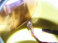
Yes! Since the foil is conductive & adhesive on one side you'd only need to cut a small strip,peal off the protective layer & wrapp it just about 1mm sticking out of the capsule.Now when you bend the top of the foil it will cover the rim of the capsule as well. Then solder the wire to the 'sected ground trace & the foil covered case together as you would normally.
Attachments

Last edited:
I have some thin copper tape lying around and I wrapped some around a pre modded capsule just to see how it fitted and it works well! Well done, I should have thought of this myself!
Yes Bigwill,..I couldn't agree more...why didn't I think of this before?!he..he..
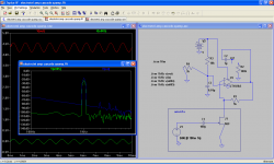
ZAP...I tried Fig;B from the circuit you supplied & and another given on Photo Bucket using;
Drain R = 4.7k
Source R = 4.7k
DC blocking/op cap on Source =470nF (0.47uF)
However,using 1uF-10uf elect.caps on the source/op,I found the bass a little undefined or "sagging".Further,this didn't help much since my input buffer is a series-non inverting-high impedance opamp circuit,hence 470nF feels just right.
The mic works very well indeed! Thanks.
Last edited:
I use about a 1 cm of desoldering braid, spread out the strands at one end, and wrap around the aluminum case of the microphone. then slip on a piece of shrinkwrap and shrink down to hold the wires of the braid against the case. Because there are so many wires in the braid, at least one of them will make a good connection with the case.
Now I can solder to the other end of the braid without worrying about overheating the cartridge and without destroying the airseal by cutting away part of the case for soldering. Seems to work well, and most diy have desoldering braid and shrink wrap tubing.
Now I can solder to the other end of the braid without worrying about overheating the cartridge and without destroying the airseal by cutting away part of the case for soldering. Seems to work well, and most diy have desoldering braid and shrink wrap tubing.
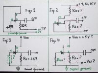
be aware that the Nfets in these capsules have diode from source to gate for biasing, and by nature of the nfet there are diodes from gate to source and drain. at low supply voltages that diode capacitance is the major attenuator and the main source of distortion due to the no linear voltage vs capacitance. for a constant gain keep the dc voltages always the same on the capsule.
You can actually buy braided grounding stocking from many elec.component suppliers. They're available from 2-4mm to really large diameters. a 8mm one should be just fine.
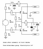
WM61 a in a Balanced Configuration
Here is a schematic og WM61 capsule wired for balanced input! The entire article can be found on
Suite101.com: Online Magazine and Writers' Network
PS😛lease note that the "Caps" are drawn wrong,but the orientation is correct!
Here is a schematic og WM61 capsule wired for balanced input! The entire article can be found on
Suite101.com: Online Magazine and Writers' Network
PS😛lease note that the "Caps" are drawn wrong,but the orientation is correct!
Attachments
Last edited:
Isn't the adhesive side insulative?Yes! Since the foil is conductive & adhesive on one side you'd only need to cut a small strip,peal off the protective layer & wrapp it just about 1mm sticking out of the capsule.Now when you bend the top of the foil it will cover the rim of the capsule as well. Then solder the wire to the 'sected ground trace & the foil covered case together as you would normally.
Isn't the adhesive side insulative?
It seems to conduct pretty well, which is a useful property!
Isn't the adhesive side insulative?
No!...it's conductive adhesive & hence conducts very well indeed! I've wired 10 capsules without destroying any of them!
I bought this conductive-adhesive-copper foil on the E-Bay, of course these are available as non conductive too.So make sure that you order/buy only the one with the conductive adhesive on the back.
I gather,these foils can be bought from "home gardening stores"..too as these are used to protect plants & flowers from snails, by running weak electricity through them!
Last edited:
THE SECRET LIFE OF ELECTRET MICROPHONES!
Here is a link which I think would be very useful to all those who want to know more about the inner workings of an electret mic.
http//www.openmusiclabs/learning/sensors/electret microphones
Here is a link which I think would be very useful to all those who want to know more about the inner workings of an electret mic.
http//www.openmusiclabs/learning/sensors/electret microphones
Last edited:
- Status
- Not open for further replies.
- Home
- Design & Build
- Equipment & Tools
- Linkwitz Mods On Panasonic WM61A Mic