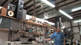
I have found this man...it looks a very old fellow..... but i could not find the schematic... i always had some suspection i could modulate a series pass voltae regulator, or a shunt regulator..... well...this man did it a long time ago.
His name is John Bedini .... a want schematic or at least the topology to give it a try.
Of course it is a class A amplifier having the linear regulator modulated...this is clear, i want schematic or some informations that become a clue to me to figure out how to create a schematic.
Thanks in advance by your kindness to help me.
https://www.youtube.com/watch?v=JrVodqUrgmQ
regards,
Carlos
Attachments


Last edited:
I got bored before he got to the end, but if it is an amp based on a linear voltage regulator, that has been done before. There are some threads about it here somewhere.
The basic thing is to remember that a linear regulator is can be used as a three-terminal device like a transistor or a FET, except that it has a different 'Vbe' or 'Vgate', namely -1.2V with respect to the output.
The rest is standard electronics engineering.
Jan
The basic thing is to remember that a linear regulator is can be used as a three-terminal device like a transistor or a FET, except that it has a different 'Vbe' or 'Vgate', namely -1.2V with respect to the output.
The rest is standard electronics engineering.
Jan
Thank you Jan Didden.
Boring voice in the video...yep.... the man is old and he looks weak... at the end we have a nice song played with the unit...the final was important...maybe the after boredon moment you could not listen.
I figured out these clues...i would like a little bit more about.
If anybody else can and want to help...please...go ahead.
regards,
Carlos
Last edited:
At the end of the video you can listen a Brazilian song reproduced
And i have this song here.... also i use very good power amplifiers and transmission line speakers to listen....i found the recorded audio quality very good, reason why i am interested in such kind of amplifier.
I know the song and how it plays.... with a little aid of imagination (because all passes through my own audio system) i can suppose the amplifier is excelent.
regards,
Carlos
Boring voice in the video...yep....
Carlos
Well its not the voice but he talks a lot and doesn't say anything about the amp.....🙂
Jan
Yes....he do not want us to know the circuit
He wants to demonstrate but do not want to give us clues.
A pitty...the guy must be very old...the know how will die with him.
It looks a Death of Zen style of amplifier, using modulation into the regulators or maybe not.... it looks 5 amperes and 12 volts circulating into each channel.... maybe nothing more than that...you know..the best secret is something that is not a secret but people believe it is a secret...maybe a copy...something usual, normal and common.... and he maintain the secret...because cannot be revealed.
I hope some friend of him will read...then will tell him.... as a result, he may come to prove i am wrong...and he must show the schematic to prove that...or i will not believe.😀
regards,
Carlos
Attachments


Last edited:
Guys show some respect! you want his ideas but you disrespect the guy! ...not cool in my book...john bedini like many of the rising boom of the 70's with audio equipment and ideas is a legend ...you may not like how his stuff plays but interesting non the less...this topology amplifier only will drive the much more higher sensitive speakers...only 5watts on hand i believe...
Lawrence
Lawrence
Indeed everyone deserves respect! Have not seen an offending post, must have been removed, but it's a no no!
Jan
Jan
The schematic can be found here
http://www.diyaudio.com/forums/chip-amps/176052-now-regulator-chip-jlh-amp.html
Mona
http://www.diyaudio.com/forums/chip-amps/176052-now-regulator-chip-jlh-amp.html
Mona
Yes voltage regulator chips could be used like transistors but a bad transistors... Nothing special about it.
Yes voltage regulator chips could be used like transistors but a bad transistors... Nothing special about it.
I think that if you look at the data, they are very good transistors, at least for audio. Very high gain.
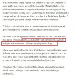
Bedini has a couple of US patents on battery charging technology. His BIG IDEA seems to be that if he hits the battery with a really really large current pulse, this will break up sulfate deposits on the electrodes. Patent 6677730 uses a bank of capacitors to supply the current pulse, while Patent 7990100 uses an inductor to supply the current pulse.
When he's not hitting the battery with pulses, he's charging it with constant current. He gets this by using a voltage regulator IC, driving a known and constant resistance. Ohm's Law tell us that I = V/R. If both V and R are known and constant, then I is also known and constant. By far the most common implementation of this idea uses the LM317, because it has the smallest V (1.25 volts), giving the smallest power dissipated in the (IC + resistor) current source.
At these places in the video, Bedini points out a few features of the amplifier:
_
When he's not hitting the battery with pulses, he's charging it with constant current. He gets this by using a voltage regulator IC, driving a known and constant resistance. Ohm's Law tell us that I = V/R. If both V and R are known and constant, then I is also known and constant. By far the most common implementation of this idea uses the LM317, because it has the smallest V (1.25 volts), giving the smallest power dissipated in the (IC + resistor) current source.
At these places in the video, Bedini points out a few features of the amplifier:
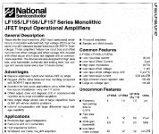
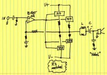
- 2:29 ... the use of a "BiFET" operational amplifier (an archaic term)
- 2:40 ... an output "Noble" network. Yes that's what he says! (not "Zobel")
- 2:49 ... the amplifier's output is capacitor coupled to the loudspeaker load
- 7:40 ... an inductor is placed in series between the amp and the speaker
_
Attachments
Member
Joined 2009
Paid Member
Hi Carlos - great to see your brain is ticking away !
Voltage regulators - as we all know, they are just amplifiers of course ! Usually with -ve feedback for low output impedance. I always view them as Power Op-Amps.
The good thing is that they are made in huge quantities, so you get them very cheaply - great for experimenting. Are we going to be treated to a DX Corporation Regulator Amplifier ???
Also available these days are small switching regulators, for higher efficiency but these may not be audio-friendly.
I think that if you look at the data, they are very good transistors, at least for audio. Very high gain.
What`s th Ft of the LM317 for instance? I have looked long time ago when the member "Circlotron" did his experiments with them but I didn`t seen it. What parameters and graphs you are talking about?? 😕
Last edited:
Hint
Destroyer X
I may have a boring voice because of chronic laryngitis of which could not be helped at the time. And I’m not a week individual as you suspect and yes I’m a lot older then you and many others here. I do not frequent groups like this because of the disrespect and the picking apart things. However, I will give you one hint it’s not full complementary as suspected. It’s a balanced Quasi circuit and make no mistake about the power as it can drive 1 ohm speakers from 1Hz to 500Khz proven since the late 60’s It was shown to John Iverson and Don Frick who were building Class A amplifiers at the time . The reason it was shown to John was he had a speaker most Amplifiers could not drive. The Amplifier on the bench can charge batteries all day long so that gives you what kind of impedance it can work with. The JBLs were at 8 Ohms and the power was set for no more than 10 watts RMS the amp has a gain of 17 and the output capacitor is not needed at all. The regulators are K series metal cases good luck getting them unless you find them on E-Bay premium price. The Amplifier was built by Me and Stewart Hegeman, I did show it at Chicago CES to Saul Marantz and Sid Smith who were very good friends. I demonstrated it on stacked Dahlquist Speakers I think about 2 ohms it drove them to ear busting level for the size room. Nobody could tell which amp was on; they did not even know that series pass modulated regulators sounded like that. I suggest you look into the LT 1083 and study the circuit inside the regulator. I never give out circuits I don’t need people picking them apart because of topology or my use of parts. I have never given up on audio and you have a few old ones here who know what audio is and what to do with it. I have built regulators discreet and they do basically the same thing and sound excellent if the circuit is correct. The BI-fet or J-fet whatever term you want to use works the best because of the drivecapability. The other thing is you will catch much more information with honey but the disrespect of this forum is incredible when people do not understand technologies that are unconventional in any form. Being skeptical is not having the understanding to move forward and sends you backwards with new things. You can find many inventions thrown by the wayside because of that not everything is in the textbook. Yes you can calculate voltage and currents but that does not mean it is going to work on the bench without changes, calculations do not make sound. Hope you find the fountain of youth and never get sick and old cause you will find out what it is. And nothing will be lost it’s all documented. Good Luck on your quest but it is done very unconventional you must think outside the box on this one since you’re limited by the voltage input. You might look at John Iverson’s grounded bridge amp for some clues.
John
Boring voice in the video...yep.... the man is old and he looks weak... at the end we have a nice song played with the unit...the final was important...maybe the after boredon moment you could not listen.
I figured out these clues...i would like a little bit more about.
If anybody else can and want to help...please...go ahead.
regards,
Carlos
I do not frequent groups like this because of the disrespect and the picking apart things. The other thing is you will catch much more information with honey
but the disrespect of this forum is incredible when people do not understand technologies that are unconventional in any form. Yes you can calculate voltage
and currents but that does not mean it is going to work on the bench without changes, calculations do not make sound.
Thanks so much for participating here, and please ignore those who have closed minds. That "ignore" option on your control panel is meant to be used.
Not a closed mind .... but -
the IC's involved have very poor psrr at the higher end of (Vout) ,
and poor psrr at higher frequencies.
The extra support circuitry needed to compensate for this might
negate the amp's initial simplicity.
The IC's original intended design use and it's 50 internal components
also might make for a less than optimal audio experience.
PS - the positive is the integrated over-current circuitry.
If you buffered these regulators , you might have something.
OS
If you buffered these regulators , you might have something.OS
Can you post a sketch of what you have in mind?
I'll describe it.
Run the regulators High Z. Buffer with a discrete stage.
OS
OK, so the regulators would be a driver stage.
- Status
- Not open for further replies.
- Home
- Amplifiers
- Solid State
- Linear Regulator Audio Power Amplifier, do you know something about this?