I have built this power supply ( Power Supply - EasyEDA ) and am supplying it with an 250va 18v transformer. It appears to power up ok, but the output voltage tests at about 58v DC. Each secondary winding on the transformer tests at 20v with no load. Does anyone have any ideas what might be causing this problem.
When you rectify an AC voltage, the resulting DC is 1.414 times the AC value. 1.414 is the square root of 2.
28 volts is the peak value of the sine wave, 20 volts the rms value.
So a 20 volts AC winding (20 volts RMS) will produce 20*1.414 which is approx 28 volts DC or in your example a total of around 56 volts between the two rails.
Transformers are normally specified at full load current and so the off load voltage will be higher, the exact amount being determined by the 'regulation factor' which is a normally given as a percentage and quoted in the specs for the transformer.
That PSU requires two secondaries. It is also very important to connect all the grounds when testing the amp boards.
ok, I'm a little confused. The power supply is intended to be used with the circutbasics lm3886 amplifier boards (A Complete Guide to Design and Build a Hi-Fi LM3886 Amplifier - Circuit Basics ). but when I hooked up the first channel it let the blue smoke out of the chip, what am I missing?
Its not easy to change the voltage output by a high power transformer.
Best thing to do is pop it on ebay then buy the right voltage transformer.
You can work back from rectified voltage to transformer voltage by dividing DC voltage by 1.414
Best thing to do is pop it on ebay then buy the right voltage transformer.
You can work back from rectified voltage to transformer voltage by dividing DC voltage by 1.414
I am using a transformer with dual secondaries ( Avel Lindberg Y236651 250VA 18V+18V Toroidal Transformer)
all of the grounds were connected when I tested the amp board, is it possible that a bad ground connection was the problem?
all of the grounds were connected when I tested the amp board, is it possible that a bad ground connection was the problem?
Perhaps you can post some photos of your build.
Attachments
Last edited:
Important that the power ground and signal ground (yellow and light green) are connected to the PSU ground.
At this point, it could be anything. You are not the first to have problems with this design. best not to connect the amps until you figure out what is wrong with the PSU.
At this point, it could be anything. You are not the first to have problems with this design. best not to connect the amps until you figure out what is wrong with the PSU.
Do You have genuine LM3886 chips ? Where did You buy them ? China ? Are the chips heatsinked ? Is the chip tab insulated from the Heatsink ?
when I hooked up the first channel it let the blue smoke out of the chip
Were you careful with the polarities of both supplies when hooking them up?
Supply #1 has the + to U6, and the - to U5.
Supply #2 has the - to U4, and the + to U5.
EasyEDA - A Simple and Powerful Electronic Circuit Design Tool
Last edited:
so first thing is the power supply voltage of 58v between the rails OK? or is there in-fact a problem in the power supply?
The chips are real lm3886TF chips from mouser, they are the isolated veriety
the chips are heat-sinked to the case, they but blew up immediately, did not slowly overheat.
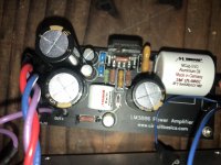
Below is a picture of the setup, after I took it back apart, I'm not sure it will be much help, but here it is. The board with the heatsink in the power supply case is a second 12v power supply, not part of the amp PSU. the Red is v+ Purple is V- Blue is GND. there are 2 ground wires in each umbilical.
The chips are real lm3886TF chips from mouser, they are the isolated veriety
the chips are heat-sinked to the case, they but blew up immediately, did not slowly overheat.
Below is a picture of the setup, after I took it back apart, I'm not sure it will be much help, but here it is. The board with the heatsink in the power supply case is a second 12v power supply, not part of the amp PSU. the Red is v+ Purple is V- Blue is GND. there are 2 ground wires in each umbilical.
Attachments

I'm far from an expert but you need a negative rail voltage and a positive rail voltage. Put your black lead on the ground and measure positive and negative outputs. You may want to rethink your case your PCBs are on standoffs I hope and not just propped up. I would disconnect everything and work your way forward starting with the transformer then power supply PCB than forward. And where did you by your components from? If your chip shorted that quick then somethings hooked up wrong or is shorted out.
Thanks for posting some photos, it answers a lot of questions in one go. First thing that comes to mind is the tabs of the diodes are internally connected, check that the tabs are not making contact with each other.
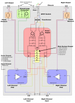
The power supply in your link in post #1 shows two separate supplies.
They are separate because each is shown as being fed from a single winding from the transformer.
Each will produce a DC voltage equivalent to 1.414 multiplied by the applied AC voltage. So in your case 28 volts DC from the measured 20 volts AC.
It is important to note that the two transformer windings (as drawn) are separate and have no connection between them.
At the right hand side of the diagram you therefore have two identical 28 volt DC supplies. If you now connect the two in series by connecting the two middle plugs on the diagram together (so U10 to U7) you change the supply into a split or dual rail type.
That centre point is now ground and you have +28 volts at the top and - 28 at the bottom.
Those values are perfect for the LM3886.
To prevent damage to the chip when testing add a small mains filament bulb in series with the incoming mains supply. Use something like a 60 watt bulb or smaller. That will limit current in the event of a fault and hopefully save the chips from failure.
Are the white and green wires on left connected together? The EMI filter looks dangerously close to the chassis and board.
The power supply is grounded to the chassis through the ground lug on the EMI Filter, Which is located directly under the negative from the power lead in picture. both the ground and negative connection are shrink wrapped, and i just double checked they are not shorted.
the power voltage from rail ground is reading at 26 and -26 volts, double checked showing the same voltage between the rails and the case. The same voltages also appear between the power leads, and the amplifier case so the power supply ground seems OK.
I just checked, none of the tabs on the diodes are touching, I would think if they were my main fuse would blow (3A slow blow) correct?
the power supply is board is mounted on 10mm standoffs. The case did get a little tighter than I anticipated , but Nothing is shorting between the boards that I can find.
All of the components came from Mouser, or Parts Express, nothing from Ebay, or other questionable sources.
It seems like the power supply is ok to me correct? I'm Beginning to suspect the ground connections within the amp case. any other suggestions?
I'm thinking of redoing the arrangement to have one umbilical caring power, and the other ground, and a more traditional star ground with all connections through a single bolt on the amplifier chases. that would eliminate the risk of one of the connections pulling loose from the main ground unseen.
The lightbulb in the power cord acts as a current limiter? does it dim or give other indications of a fault?
any suggestions on what else to test while I'm waiting on the new LM 3886 chips in the mail? I would prefer not to cook the new ones.
The bulb would normally be either not lit or very dim corresponding to little current draw. If a fault situation is present then the overall current rises and the filaments resistance rises rapidly limiting the current and lighting up in the process.
If you measure the filament resistance of a bulb when cold then you will see how low it is. Providing you don't pull much current the resistance stays low and so overall it has little impact on the circuit.
Grounding issues can easily provoke instability and that can draw destructively high currents.
And yes, your PSU voltages seem correct.
- Status
- Not open for further replies.
- Home
- Amplifiers
- Power Supplies
- Linear power supply voltage too high