Hello all! I’ve lurked these forums for over a decade, but have sortof met my match with this 10amp, 16v Power-One PSU. (No schematics available)
This power supply is being used with a Soundworkshop Series 34 studio console. When all modules are connected to the PSU, it draws about 8 amps from the PSU.
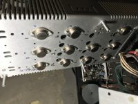
My problem is with my -16v rail. When all 3055’s are in circuit, as soon as there is a current draw, -16v rail ceases to function. This is happening somewhere before the 723 voltage regulator IC. However, if I removed one of the 3055’s associated with the -16 rail, it supplies power to the board, no problem. The PSU does (understandably) run hot, and it is probably inadvisable to run for any length of time..
I’ve tried swapping out with other 3055’s, but no luck. I ordered a bunch of newer 3055’s from Allied, but I would really prefer to NOT shotgun this repair and understand better what is happening exactly.
The whole board was recapped and each transistor, thyristor and diode have been taken out of circuit and tested with a diode tester. The 723 regulators are also new. Got a feeling a “good” 3055 is testing good out of circuit and failing under load, but I dunno. Photo is of the PSU running with said 3055 removed.
Thanks in advance!
-janah
This power supply is being used with a Soundworkshop Series 34 studio console. When all modules are connected to the PSU, it draws about 8 amps from the PSU.
My problem is with my -16v rail. When all 3055’s are in circuit, as soon as there is a current draw, -16v rail ceases to function. This is happening somewhere before the 723 voltage regulator IC. However, if I removed one of the 3055’s associated with the -16 rail, it supplies power to the board, no problem. The PSU does (understandably) run hot, and it is probably inadvisable to run for any length of time..
I’ve tried swapping out with other 3055’s, but no luck. I ordered a bunch of newer 3055’s from Allied, but I would really prefer to NOT shotgun this repair and understand better what is happening exactly.
The whole board was recapped and each transistor, thyristor and diode have been taken out of circuit and tested with a diode tester. The 723 regulators are also new. Got a feeling a “good” 3055 is testing good out of circuit and failing under load, but I dunno. Photo is of the PSU running with said 3055 removed.
Thanks in advance!
-janah
Attachments
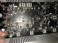
See the burned open resistor, R49?...
PS, do yourself a favor & put some heatsinks on those two three-pin devices, plenty of room...I don't trust de-rated values, heat is the insidious enemy.
----------------------------------------------------------------------Rick...
PS, do yourself a favor & put some heatsinks on those two three-pin devices, plenty of room...I don't trust de-rated values, heat is the insidious enemy.
----------------------------------------------------------------------Rick...
Last edited:
Yep! That resistor has since been replaced. Previous owner put a 3055 where a center tapped TO3 rectifier should have been. Old picture and I didn’t catch it. Sorry!
That 723 was ALSO replaced. It was fried. This was a pic of the board shortly after I recapped it, and before I began troubleshooting issues with transistors and ICs.
The fault does not follow the regulators. I have not been able to replicate the fault on the +16v rail with 3055 or IC swapping. The only thing that I have not replaced are a TIP29 and its PNP equivalent, but both tested good.
It might be worth mentioning that the PSU has thyristor OVP, but that component was also replaced.
It might be worth mentioning that the PSU has thyristor OVP, but that component was also replaced.
Check/confirm the non-obvious culprits, like that 0r33 resistor next to R10 , is that just dirty or heat stressed and possibly off value?
This supply has adjustable current limiting functions for both the positive and negative outputs and it looks like they have been have been modified.
The positive current limit is adjusted by R17 and activated by SCR1 which is missing (unless it's on the other side)
The negative current limit is adjusted by R32 and activated by SCR2 which has the extra wires attached.
You can also check to see if the current limiting is on if SCR2 is on when the negative rail goes down.
Better to get a schematic and rewire it as the manufacturer intended.
Thank you everyone for your replies, I really appreciate it.
Mike, your suggestion turned out to be fruitful. I tested the 0r33 resistors and all tested a nominal .3 ohms EXCEPT for R56 and R57 which tested at 9.3 ohms. These resistors are in circuit with the -16v rail and base/emitter of Q11. When a 3055 is put into circuit at Q11, the -16v rail faults. I think we're on to something, now! I've also noticed that many of the 1/2 watt resistors have drifted in value. Some just a bit, but some quite a lot. Wondering if it would not be a bad idea to just replace them all? This unit does generate quite a bit of heat.
techtool, there are modifications to the circuit, but this is how it left the factory. I've seen other power supplies of this same make and model, and they all lack SCR1 with the anode of SCR2 connected directly to the +16v rail. There is not schematic available for this PSU, unfortunately. I have contacted Bel Power Solutions (FKA Power-One), but have not heard back.
Resistors are cheap - why not change them?
Many projects, nowhere near enough time 🙂
>The positive current limit is adjusted by R17 and activated by SCR1
>The negative current limit is adjusted by R32 and activated by SCR2
Interesting "Overcurrent" scheme. Supplying too much current? Short the output to ground... That'll show 'em!
I have a 5V and a couple 24V versions of this circuit. The 5V kept firing the OCP and I'm sure I wasnt loading the thing too high. I actually thought it was OVP, so I reduced the voltage from 5.18 to 5.0V. Still did it.
With the SCR activated, the little 5V supply would just cook into a short circuit condition indefinitely until AC power was cycled. I assume you're supposed to have a fuse on the AC, which would blow. Being an experiment at the time...
If OVP isnt part of the SCRs function, I'd just get rid of the SCRs.
An OV condition makes sense to instantly crowbar the output. OC? What were they thinking? Oh yeah, just blow the fuse. Nice. Well, the circuit has been some kind of industry standard for 55 years, so there's proof of technique validity.
Last edited:
R49 looks fried (near to R56/57 - the 2 which measure too high). Looks like that is a problem area.
It turned out to be The .22 ohm R56 and R57. When removed from circuit they tested as having a resistance in the tens of thousands of ohms. Replaced all 16 of them, along with some other resistors that measured out of spec and new 3055’s for good measure. I’m sure it would have taken me awhile to think to check those if it had not been suggested here 🙂 Thanks!
- Home
- Amplifiers
- Power Supplies
- Linear power supply help!!