I have found another regulator that uses this idea here (PDF, page 4)... So I don't think it's too dangerous.
One might suggest putting a capacitor across R3 instead to prevent oscillation, but this is not the way as it actually increases the chances of oscillation because it is at the very most sensitive part of the circuit and easily causes much delay due to R3.
I would also suggest that this part of the circuit if not the whole thing should to be inside a Faraday cage.
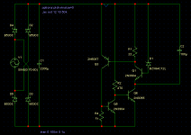
Here are the current specs as simulated:
Output voltage (Vout): 33.5V
Vout Offset from 0A-2A (DC constant-current): ~50uV
Ripple at 2A: ~200uV
Line ripple with a sine-modulated load current between 0A and 2A at 20Khz: 700uV.
Max. Current rating is over 2A, but I have not measured much that far. A current limiting circuit will be necessary, because the circuit oscillates when pushed past its limit. The way to increase the limit is to increase R1. However, I do not know exactly how this will affect performance.
Also, the problem with the voltage rising with load currents below 0.2A doesn't exist anymore.
Attached are two graphs:
The first is the output ripple vs. frequency.
The other is the output trace with a load current modulation index of 2A.
PS: It's finally happened. I was staring at a resistor blankly for a few minutes and then I thought: Green-Blue-Orange... 56K... 🙂
- keantoken
One might suggest putting a capacitor across R3 instead to prevent oscillation, but this is not the way as it actually increases the chances of oscillation because it is at the very most sensitive part of the circuit and easily causes much delay due to R3.
I would also suggest that this part of the circuit if not the whole thing should to be inside a Faraday cage.
Here are the current specs as simulated:
Output voltage (Vout): 33.5V
Vout Offset from 0A-2A (DC constant-current): ~50uV
Ripple at 2A: ~200uV
Line ripple with a sine-modulated load current between 0A and 2A at 20Khz: 700uV.
Max. Current rating is over 2A, but I have not measured much that far. A current limiting circuit will be necessary, because the circuit oscillates when pushed past its limit. The way to increase the limit is to increase R1. However, I do not know exactly how this will affect performance.
Also, the problem with the voltage rising with load currents below 0.2A doesn't exist anymore.
Attached are two graphs:
The first is the output ripple vs. frequency.
The other is the output trace with a load current modulation index of 2A.
PS: It's finally happened. I was staring at a resistor blankly for a few minutes and then I thought: Green-Blue-Orange... 56K... 🙂
- keantoken
Attachments

Hi,
Your circuit -- I will build (lashup more like) and try it. I am only going to use a 0 to 30 volt PSU as a source and a selection of different voltage zeners for D1.
Walt Jungs circuit puts the reference in the emmiter side of the error amp, the output voltage set by the feedback network R861 and 863. It's similar- ish to yours but look how Q853 is connected (collector).
Thank you! 🙂🙂🙂 I am saved.
Yes, I guess Q853 is connected differently... Hmm.
My biggest problem is that I'm only 14 (or 15? I forgot 0_0)and my mother doesn't want me connecting my circuits to the wall outlet. While it is damaging to my pride to reveal this, I would rather that those reading this not think I'm lazy. 🙂
I am contemplating making a 120V step-up converter, naturally of my own design since I can't find any of my NE555s and I only really have transistors, capacitors, and wire. Problem is that I won't really get enough current out of it to do any serious tests.
Once again, thank you.
- keantoken
Well out of interest, here is what happened. The output is a sawtooth the amplitude of which is set by the zener. See picture, this is 12 volts peak/peak amplitude at around 125 khz. The frequency varies as the input volts is altered.
Sounds like you need a proper stabilised, fully adjustable lab PSU and (maybe 🙂 ) try something a bit less ambitious to begin with. An adjustable PSU was one of the things I made first, from a design in a mag -- many years ago now.
Providing you can get someone to check any mains wiring first, at some point you have to go for it and have the confidence that what you have done is safe and correct.
Good luck with it all
Regards Karl
Attachments

What components did you use? It looks to me like R3 was disconnected. In this circuit it is important to use components with as low parasitic capacitance as possible... I am currently trying to build it. I managed to pull a 12V zener out of a computer PSU, so it will be powered by 24V out of four 6V lantern batteries.
I'll play around with it and see if I can make it work... And if not find out why it doesn't work.
- keantoken
I'll play around with it and see if I can make it work... And if not find out why it doesn't work.
- keantoken
I used TIP41A for the pass transistor and BC546 and BC307 for others. R1 initially at 82 K . With a 24 volt supply the regulation was poor under load ( I used 15 ohm as a load ) and R3 was 27 ohm. Reducing R1 down to 10 k improved the regulation greatly.
At 82 K the output fell by a volt or more when loaded with 15 ohm.
The only way to stop the oscillation ( at a basic level without adding caps etc) was to remove Q5 and connect the collector of Q7 to the emmiter of Q3.
Regards Karl
At 82 K the output fell by a volt or more when loaded with 15 ohm.
The only way to stop the oscillation ( at a basic level without adding caps etc) was to remove Q5 and connect the collector of Q7 to the emmiter of Q3.
Regards Karl
Hmmm...
I think it is a good idea but when it gets to it the PUT pair is just to sensitive to be used in this way. I'll keep working though, and see if I can figure something out... It worked great in the sim though. 🙂
Thanks for your help, mooly.
- keantoken
I think it is a good idea but when it gets to it the PUT pair is just to sensitive to be used in this way. I'll keep working though, and see if I can figure something out... It worked great in the sim though. 🙂
Thanks for your help, mooly.
- keantoken
keantoken,
The "PUT pair" is really more like an SCR, because the on resistance of an SCR is much lower than a PUT.
This circuit will inherently oscillate due to the latching action of Q5 and Q7. When these transistors turn, on the base emitter junction of Q3 becomes forward biased and the emitter current of Q2 becomes Beta_Q3*(56-2.8)/R1. In addition, the base of Q1 is pulled low and the zener no longer conducts. Then the cycle repeats. C2 and the natural response time of the circuit components will determine the oscillation frequency.
In order to get this circuit to work, delete Q5 and increase the value of R3. Q3, Q4 and R2 aren't required either. I know, this looks just like any other seires pass regulator.
As another point all power supplies have some fairly large capacitor right at the output terminals.
Rick
Keantoken,
Ops, I made a minor error. When Q5 qnd Q7 turn on, the emitter current of Q2 will be limited to Vbe3/220 or about 3 mA.
The rest of what I said is correct.
Rick
Ops, I made a minor error. When Q5 qnd Q7 turn on, the emitter current of Q2 will be limited to Vbe3/220 or about 3 mA.
The rest of what I said is correct.
Rick
Okay, what you say makes perfect sense. I only tried to use the PUT pair in this way because I observed (on the simulator 😛) that if the base current was regulated precisely, it would not latch.
I've just got some perfboard from Radioshack and some more transistors to smoke. 🙂 Plus some silver-bearing solder, and a 2N3055 that maybe with some persistence I can rig into a PSU of my own qualifications. 😀
So I'll be experimenting a bit more with real life. 🙂 🙂
A soldering iron is still on the list, however. For now I have to make do with a butane microtorch.
I think I'll start by making myself an LTP with two transistors and a CCS and go from there. Learning should be much easier now that I know how to use my oscilloscope.
I'm sorry if I'm a bit pesky, but strangely enough I can only learn at my own pace. Now that I've finally gotten comfortable with that fact, maybe I can finally learn something. 🙂
- keantoken
keantoken said:Hi.
I've been tweaking this design for quite a while now, and want to run it by the DIY community for feedback or suggestions. I have not built it yet, for lack of parts.
------------
- keantoken
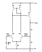
Linear Pass transistor regulator - my design
This basic model posted below is what I usually begin with.
When designing my discrete regulators.
it has
- low voltage drop, can be as low as 0.05-0.10 volt at lower currents.
- very good regulation at different input voltage levels
( because reference is fed from output voltage! see my next post attachment, for this feature )
Attachments
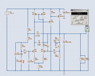
Here is one full implementation.
The trick here is the R1 = startup 1 Mohm resistor.
After this the reference is biased from output precise voltage level.
Via the diode D1.
This very version is for regulating extremely precisely from a 9 VDC battery.
Which can have a voltage going from 9.60 ... downto ~ 7.80 volt
when battery is close to empty.
Notice 😎
7.57 Volt in ... and ... 7.50 Volt out ... at 20 mA output.
Suitable for hifi Op-Amp circuits, for example.
Lineup
Attachments
Hi lineup. 🙂
Hmm. I've seen regulators using an LTP as a comparator, but for some reason I didn't like the idea... I think I'll abandon my previous design. It'll stay in my archives for interest, though...
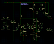
At any rate, I coughed this up shortly after reading your post. D8 is to cancel the extra voltage drop of Q8 in the voltage reference, with D6 to equalize the currents in the LTP. C10 is required to keep the circuit from oscillating. :/
This is the first thing I though of. The CCS of the LTP is powered from the voltage reference. I'm not sure if Q9 is needed, but it extends the HF response of Q10, which is why it is there.
Is my logic correct so far?
At any rate, thanks for the circuit.
- keantoken
Hmm. I've seen regulators using an LTP as a comparator, but for some reason I didn't like the idea... I think I'll abandon my previous design. It'll stay in my archives for interest, though...
At any rate, I coughed this up shortly after reading your post. D8 is to cancel the extra voltage drop of Q8 in the voltage reference, with D6 to equalize the currents in the LTP. C10 is required to keep the circuit from oscillating. :/
This is the first thing I though of. The CCS of the LTP is powered from the voltage reference. I'm not sure if Q9 is needed, but it extends the HF response of Q10, which is why it is there.
Is my logic correct so far?
At any rate, thanks for the circuit.
- keantoken
Attachments
keantoken said:Hi lineup. 🙂
Hmm. I've seen regulators using an LTP as a comparator, but for some reason I didn't like the idea... I think I'll abandon my previous design. It'll stay in my archives for interest, though...
At any rate, I coughed this up shortly after reading your post. D8 is to cancel the extra voltage drop of Q8 in the voltage reference, with D6 to equalize the currents in the LTP. C10 is required to keep the circuit from oscillating. :/
This is the first thing I though of. The CCS of the LTP is powered from the voltage reference. I'm not sure if Q9 is needed, but it extends the HF response of Q10, which is why it is there.
Is my logic correct so far?
At any rate, thanks for the circuit.
- keantoken
Your regulator is rather advanced, compared to my circuit.
You fead reference from INPUT voltage. I from the Output.
This should give better line regulation for me. ( in-sensitive to input ripple and voltage variation )
D1, 1N4148 is the trick in my circuit. Very much Nice feature.
As I wrote in my post.
When I tested that circuit in Sim.
I adjusted for 7.500 Volt at like 8.000 Volt input.
Using 20 mA load.
Not until I got downto 7.560 Volt input, the meter shows
7.499 Volt output ( ~ 0.01 % change )
Now I tested to raise the input voltage. Same load 20 mA.
Not until I came to 30 Volt input level,
the meter flips from 7.500 to 7.501 Volt ( ~0.01 % change )
This means, my circuit has an ENORMOUS Line Regulation.
Necause the bias of Reference, is al the time coming
from 7.500 .... the output
Load Regulation, improves the higher GAIN we have.
This is also the reason I have added a PNP Driver to my output BD140.
I use only one output transistor (PNP). You use 2 NPN followers.
This will theretically, give you better load regulation. ( in-sensitive to LOAD current variations )
On the other hand, my circuit was itended for minimum voltage drop, from a battery + low current operation.
To my circuit we can add a Power Transistor (or Darlington, as you do )
as a follower.
This give +0.7 Voltage dropout voltage, but give out considerably higher current.
Your circuit will work, keantoken.
You may perhaps simplify it a bit.
------------------
Credits to you, for using a somewhat REAL SUPPLY ... for simulation.
We have guys 😀 at forum, like PMA etc. that posts horendous figures simulations.
They have just not realized, that the Biggest error source to their sims
is that supposing Ideal Voltage Soure
while using same Ideal Supply for Input VAS + Output Power stage
will screeeew their figures.
==========================================
😎
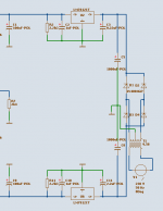
I attach what I use, when I want some better Reality, than PMA.
A simulated REAL Power supply.
Using numbers in the transformator Inductor core,
that I have measured on one Real Trafo I have.
Lineup regars
Attachments
D1, 1N4148 is the trick in my circuit. Very much Nice feature.
Okay, I give up. What does D1 do?
- keantoken
I know what Diode D1 does . Think about it ?? Where does the reference get its supply from
I know that, anyone who spends time on a regulator project usually does this. But I thought that there was something about the voltage drop caused by the diode or maybe its characteristics... Temperature compensation?
At any rate, I just put this together. It's actually no different than my first circuit except that it's simpler. It seems to work just as well too, at least in the sim. I've got it built and it's running on a 24V 4-pack lantern battery PSU. I'm not really sure if it's working correctly, I just know that I get some voltage when I flip it on. Probably something like 0.6V... At least it doesn't oscillate. 🙂
I actually fried everything but the 2N3055 when I first turned it on... Output is between ground and the collector of the 2N3055... Notice where ground is... I only did this so I could measure values on the sim easier.
- keantoken
Attachments
It works! Output stable at 13.2V into 1.2K load...
I've yet to test very far, but it looks like Q3 has problems firing at random times...
If someone else wants to test, be my guest. Hmm. I need a variable current source for testing load... How much current can a breadboard take? That would be very useful about now...
- keantoken
I've yet to test very far, but it looks like Q3 has problems firing at random times...
If someone else wants to test, be my guest. Hmm. I need a variable current source for testing load... How much current can a breadboard take? That would be very useful about now...
- keantoken
With my oscilloscope at the 1mV/Div setting, I can't see any difference in noise level between when the circuit is on and when it is off...
- Status
- Not open for further replies.
- Home
- Amplifiers
- Power Supplies
- Linear Pass transistor regulator - my design