Hi, Does anyone want to take on the challenge on how to hook this up in my circuit? Much thanks in advance!
“The topology is shown in figure 1. By inserting the switch in the return line to the power transformer I leave everything after the last reservoir cap unchanged. So there is no impact on the power supply quality and no messing up any carefully laid out ground circuitry. It can be used either with a bridge-type rectifier or a center-tapped secondary with a double-phase rectifier as shown.
With a Center Tap transformer, the board is connected between Gnd and Center Tap. With a full bridge rectifier, it is connected between ground and the gnd output of the diode bridge. Easy, simple, no risk.”
Attachments
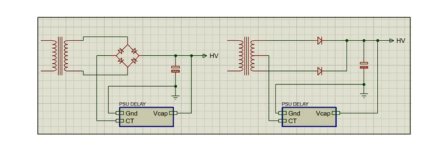
"With a Center Tap transformer, the board is connected between Gnd and Center Tap."
In this case the "Gnd" is the 6.3V CT.
In this case the "Gnd" is the 6.3V CT.
Thanks for your input and guidance. Next question, do I need two board's for a stereo amp or do I just make a connection to each B+ side of the amplifier from the board?
Ok, got it but am I hooking it up from the board to both left and right B+. Sorry for all of the questions.
I have replied in your other thread. Check that, my previous advice wasn't correct, from memory, sorry.
As to the previous post, your B+ for both channels is the same, right, so only one board needed.
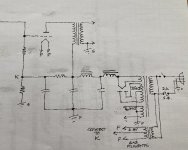
The drawing in post # 3 is correct.
Jan
As to the previous post, your B+ for both channels is the same, right, so only one board needed.
The drawing in post # 3 is correct.
Jan
- Home
- Amplifiers
- Tubes / Valves
- Linear Audio High-voltage Delay for Tube Amplifiers V4