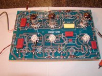
I purchased what is supposed to be a clone of a Jadis line stage that contains 3) 12AX7's per channel. It took about 15 min to stuff
as it was laid out pretty well.
It sounds good except I can't get rid of the hum problem. I am running a R*C*R*C power supply with 360volts going to feed the board. I am running 6.3VDC with a 27,000mfd cap for filtering to feed the heaters.
So far I have listened to one channel with the power and heaters unterminated on the other side.
The board has all the grounds tied together for each channel so I would assume this wouldn't be the problem.
Its actually 2 separate channels on one board.
Any ideas?
I will try to send a schematic of it
Attachments

How are you treating the tied-together board grounds with respect to input socket ground, power supply ground, and chassis ground?
SY
So far the board isn't mounted to a chassis. I have soldered RCA jacks on for the input and output terminations. The ground on these is commoned to the ground buss. My power supply ground is soldered to the common ground buss. The negative off my Bridge (heater supply) goes to the common/chassis of the power supply.
I have a stand alone power supply that I am using on it right now before building the finished product.
Do the values look to be in line? Would you suggest any changes to the circuit?
The values look fine- this is just one more variation of the old Marantz preamp. Check voltages at the plates of the first two tubes and the cathode of the CF to confirm that everything is working as it should.
I'm somewhat confused about the ground bus- is it indeed a bus or are the grounds tied together in a star? If the bus has two ends, so to speak, that may be the source of your hum.
I'm somewhat confused about the ground bus- is it indeed a bus or are the grounds tied together in a star? If the bus has two ends, so to speak, that may be the source of your hum.
I will try to send a picture of it. It might be easier to view a problem if you can see the board. I will heat up the garage and check the voltages in the different sections.
Note. Like I mentioned the board is laid out with two separate channels. It wouldn't take much to score and snap the board for mono sections.
What is your feeling on the feedback loop?
Note. Like I mentioned the board is laid out with two separate channels. It wouldn't take much to score and snap the board for mono sections.
What is your feeling on the feedback loop?
Attachments
line stage board off from overseas.problems
Where are the B+ supply bypass filter caps I dont see them
Where are the B+ supply bypass filter caps I dont see them
Re: line stage board off from overseas.problems
C108/208 and C109/209. Looks like they're mounted on the underside- I see solder joints.
jaudio said:Where are the B+ supply bypass filter caps I dont see them
C108/208 and C109/209. Looks like they're mounted on the underside- I see solder joints.
From what I can make out in the picture, there are two separate buses, one for each channel. They should only connect at a star ground at the input socket grounds as should the return for the B+ and heater feed. Make sure there are no unintended loops on the outputs, too.
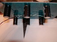
Since this is supposed to be a Christmas present for a friend I wanted to make it easier for me and I mounted the caps on the bottom of the board thus making 6 less holes for me to drill in the top plate. I am going to use stand offs to mount the board under the top plate. I figured 6 tubes don't look too bad but add 6 caps to it and it starts to get busy.
Problems...
First I don't know/remember how to calculate the cap in the feedback loop. I question the 1P value. I have I believe 330 pf in there now.
Secondly, there is a voltage pattern on the output that keeps repeating its self. The voltage ramps up to several volts positive then back to zero followed by a voltage ramp the negative way.
What I did right or wrong... I figured I would change the value of the 470K R102 resistor to a smaller value. I used 27K because I had one handy and the voltage ramp stays in the mv range now.
R103 voltage changed from .9V to 1.3V R104 changed from 17.4V
to 20.4V
Oh, I added by pass caps on each tube heater of .01mfd.
Any comments? Ideas?
Re: Re: line stage board off from overseas.problems
They can't be under - not enough space, unless the wrong value caps are mounted. May be the problem.
Jan Didden
SY said:
C108/208 and C109/209. Looks like they're mounted on the underside- I see solder joints.
They can't be under - not enough space, unless the wrong value caps are mounted. May be the problem.
Jan Didden
ling stage board off from ovrseas.problems
I see the bypass caps on the schematics but not on the picture of the board. When bypass cap dry out or fail,you'll get hum
I see the bypass caps on the schematics but not on the picture of the board. When bypass cap dry out or fail,you'll get hum
burnedfingers said:Jan
The parts sheet calls for 6) 100mfd/450V caps. I have them below the board.
OK, I see. I thought they were different ones, the board looked low on the sheet in the pic.
How loud is the hum? Where is your volume control, before the preamp? Did you try with the input shorted?
Jan Didden
Well, the 330pF with the 100k will roll your freq response off starting at 5 kHz or so. This will defenitely sound dull -😉
In fact, this may cause the ramping, what is the ramp frequency?
The 1pF is not unreasonable for ultrasonic roll off. Try the smallest cap you can find, like 5 pF.
Jan Didden
In fact, this may cause the ramping, what is the ramp frequency?
The 1pF is not unreasonable for ultrasonic roll off. Try the smallest cap you can find, like 5 pF.
Jan Didden
So I must have had a high frequency osolaton with the 470K resistor in the feedback loop?
Am I more in line with the different feedback resistor value?
Can't I leave it off (1P cap in feedback loop)since the tube amp should cover the low frequency roll off?
Am I more in line with the different feedback resistor value?
Can't I leave it off (1P cap in feedback loop)since the tube amp should cover the low frequency roll off?
Volume control is before the preamp. Tried with input shorted and still hum. Well, it(hum) wasn't super loud but you could tell it was there.
The 1 pF cap in the feedback loop is for high frequency stability. It's easiest to use a gimmick cap, which is just two one-inch lengths of wire twisted together. Heck, the feedback resistor probably already has a pF across it just in stray...
Sy
Would you suggest trying it without the cap? I have never seen a
gimmick cap so I'm not sure on making one.
What are your feelings on the resistor change I made? R102 470K to 27K?
Would you suggest trying it without the cap? I have never seen a
gimmick cap so I'm not sure on making one.
What are your feelings on the resistor change I made? R102 470K to 27K?
- Status
- Not open for further replies.
- Home
- Amplifiers
- Tubes / Valves
- Line stage board off from overseas. problems