On the subject of test methodologies, what are the gotchas/considerations/advices when using a 600R/600R audio line output transformer when used to bridge across various loads, in particular an amplifier output terminals, or a loudspeaker input terminals.
Also, what is the difference between say, 150/150, 600/600, 3K/3K, etc 1:1 coupling transformers when used between low impedance source, and high impedance input ?.
Dan.
Also, what is the difference between say, 150/150, 600/600, 3K/3K, etc 1:1 coupling transformers when used between low impedance source, and high impedance input ?.
Dan.
transformer is a ratio thing, voltage ratio is proportional to numbers of turn ratio usually called '' a ''.
impedance ratio is proportional to '' a * a '' ...... the square of '' a ''
more later ... I must quit .............
impedance ratio is proportional to '' a * a '' ...... the square of '' a ''
more later ... I must quit .............
The basics are obvious I think. The impedance refers to the impedance that gives the broadest frequency response with the lowest distortion, except when its optimized for a specific task. The maximum input on the "bridging" transformer will limit what you can do across an amplifier output. Its not a good way to get a differential input for general purpose applications. It can be a decent way to get an isolated output. If you are looking at special cases (potential transformers for HV transmission lines for example) its a good solution but not really for audio.
Thanks, I am well aware impedance of ratio...I did say ''when using a 600R/600R audio line output transformer'' and ''1:1 coupling transformers''.transformer is a ratio thing, voltage ratio is proportional to numbers of turn ratio usually called '' a ''.
impedance ratio is proportional to '' a * a '' ...... the square of '' a ''
more later ... I must quit .............
Dan.
Hello Demian....The impedance refers to the impedance that gives the broadest frequency response with the lowest distortion, except when its optimized for a specific task.
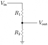
So, for a 600R/600R transformer do you mean series impedance of 600R driving the primary and 600R load on the secondary will give the best FR and lowest THD ?.
Sure, so attenuation may be required.The maximum input on the "bridging" transformer will limit what you can do across an amplifier output.

So what is optimal ?...should R1 be 600R and R2 variable, or R1 variable and R2 be 600R ?.
I'm just looking for galvanic isolation of the output of any typical audio system into various test equipments, including AD convertor, D&N set, Cro etc.Its not a good way to get a differential input for general purpose applications.
20 kHz response is fine enough for now.
Same as above ?.It can be a decent way to get an isolated output.
Thanks, Dan.
Last edited:
Dan, are you familiar with this work?
http://www.jensen-transformers.com/an/Audio Transformers Chapter.pdf
Best,
http://www.jensen-transformers.com/an/Audio Transformers Chapter.pdf
Best,
Current rating of a transformer winding is linked to wire gauge, and if overcurrent occur theat dissipated may destroy insulation or reduce transformer life.
Voltage rating of a winding is linked to the number of turn of the winding AND magnetic saturation of the core, this explain why voltage rating is proportional to frequency.
So if you have a power transformer rated at a maximum voltage of 220 volts at 50Hz, it may be used at 264 volts at 60 Hz.
For an audio tranfomer rated 2 volts at 30 Hz, saturation will occur at 1.33 volts at 20 Hz..... or 4 volts at 60Hz .....and so on ... remember if you have saturation of the core you will have distortion in your signal.
For audio transformer you must start calculation from transformer data impedance, frequency span, and power and convert to voltage & current.
- Status
- Not open for further replies.
- Home
- Design & Build
- Equipment & Tools
- Line Output Transformers Question.