The Korg B1K is a truly great-sounding preamp. One minor inconvenience is that there is quite a distinct “thump” when turned on or off, and if the power amp is on at the time then the speakers can take a bit of a wallop.
As part of my own Korg build I designed a small PC board which gave me, in addition to input switching and a 12V trigger circuit, a 4-second turn on delay and an instant turn off when power was disconnected for whatever reason. The relays switch in 4 milliseconds and draw power only while switching (latching relays) so there is no magnetic field in the relay except during actual switching.
Another person on the B1K thread was looking for a delay circuit so I offered to redesign my more elaborate board to include only the delay relay. I have now completed the circuit card layout and schematic and thought I’d post it in case anyone else was interested. It will be pretty flexible – delay time is adjustable by replacing one resistor and different power supply voltages can be accomodated by changing a different resistor. The board is just over 2.5” x 1.25” to fit in small spaces.
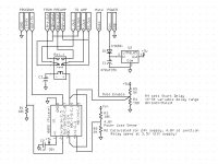
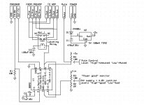
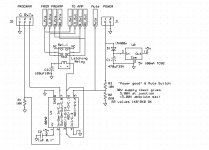
When the output is “off” the preamp is disconnected from the power amp and the power amp input center conductor is connected directly to the power amp ground via the cable’s ground shield. When the output is “on” the preamp output is connected to the power amp input. The left ground and right ground connections are separate from each other and from the power ground of the pcb.
The circuit is controlled by a really simple 8-pin PIC microcontroller in a through-hole package, the Picaxe 08M2. This PIC is easily programmable by anyone with just a little bit of knowledge and a PC if they have the necessary code to upload to the chip (which I will eventually provide). I will post the Gerber, schematic, BOM and the complete program code for the PIC so anyone should be able to duplicate this board. The PIC itself is about $3US and the programming cable is maybe $10~$20US. You can program the chip before you install it on the board or after – a programming interface is included on the board – and modify the code via the interface if you want to change the delay timing to suit your own needs. I do recommend you use an 8 pin DIP socket for the chip.
My next step is to order a set of boards from JLCPCB and verify my code before publishing.
As part of my own Korg build I designed a small PC board which gave me, in addition to input switching and a 12V trigger circuit, a 4-second turn on delay and an instant turn off when power was disconnected for whatever reason. The relays switch in 4 milliseconds and draw power only while switching (latching relays) so there is no magnetic field in the relay except during actual switching.
Another person on the B1K thread was looking for a delay circuit so I offered to redesign my more elaborate board to include only the delay relay. I have now completed the circuit card layout and schematic and thought I’d post it in case anyone else was interested. It will be pretty flexible – delay time is adjustable by replacing one resistor and different power supply voltages can be accomodated by changing a different resistor. The board is just over 2.5” x 1.25” to fit in small spaces.
When the output is “off” the preamp is disconnected from the power amp and the power amp input center conductor is connected directly to the power amp ground via the cable’s ground shield. When the output is “on” the preamp output is connected to the power amp input. The left ground and right ground connections are separate from each other and from the power ground of the pcb.
The circuit is controlled by a really simple 8-pin PIC microcontroller in a through-hole package, the Picaxe 08M2. This PIC is easily programmable by anyone with just a little bit of knowledge and a PC if they have the necessary code to upload to the chip (which I will eventually provide). I will post the Gerber, schematic, BOM and the complete program code for the PIC so anyone should be able to duplicate this board. The PIC itself is about $3US and the programming cable is maybe $10~$20US. You can program the chip before you install it on the board or after – a programming interface is included on the board – and modify the code via the interface if you want to change the delay timing to suit your own needs. I do recommend you use an 8 pin DIP socket for the chip.
My next step is to order a set of boards from JLCPCB and verify my code before publishing.
Attachments

Last edited:

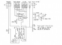
6L6 suggested that there was a better way to relay-mute the preamp (as long as DC offset is not a problem which it isn't for the Korg), so the schematic around the relay has changed. Now the preamp and power amp are connected at all times and when the circuit is muted, the always-connected signal conductor is shorted directly to ground. Thus, during play the relay is entirely out of the circuit.
Attachments
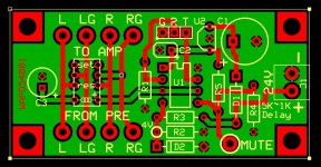
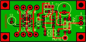
The design and programming is complete and I have built and tested two prototypes. The board has changed to reflect suggestions made regarding the relay circuit plus the elimination of an unneeded resistor and minor rearrangement of components and traces.
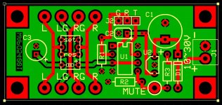
The circuit card is a tiny bit over 2.5" x 1.25" and only a few components are needed. The entire board draws about 4mA continuously plus up to 20mA more momentarily during relay operation for perhaps 10 milliseconds.
The startup delay is just under 4.0 seconds and this can be changed to any value by changing one value in the program.
The signal In/Out pads on the relay are symmetrical -- either end can be either the input or output.
Read the Notes for more information.
Attachments
-
 Delay and Mute 12 BOM.JPG46 KB · Views: 244
 -
Delay and Mute 12 Gerber.zip8.3 KB · Views: 102
-
Delay and Mute 12 Notes.pdf19.3 KB · Views: 155
-
 Delay and Mute 12 Picture.jpg242.7 KB · Views: 228
 -
 Delay and Mute 12 PCB.JPG195 KB · Views: 239
 -
 Delay and Mute 12 Schematic.JPG102 KB · Views: 236
 -
 Delay and Mute Programming Setup.jpg248.3 KB · Views: 218
Last edited:
Kinda forgot about this project until just recently. Here is the required code to program the Picaxe 08M2 chip. The .bas (basic) file is contained in a ZIP container because the website won't allow uploading a .bas file.
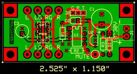
If there is any interest, I've simplified the pcb somewhat to reduce the size to 2.5"x1.0" and I can upload the gerber if anyone actually wants a marginal reduction in size.
Also I'm working on a change to make the board more flexible -- to allow any input voltage of 9V~30V rather than the currently fixed value of 24V. With the new code, the chip will recognize a supply drop of 25% from nominal as "power failure" and disconnect the output.
Attachments
Last edited:
wapo54001:
Cool project! I'd be interested in the gerber's once you refine the design to accept the broader range of input voltages.
Regards,
Scott
Cool project! I'd be interested in the gerber's once you refine the design to accept the broader range of input voltages.
Regards,
Scott
The Gerber, PCB and schematic images, and the basic program at this post supercede all previous posts and data.
This version has several improvements:
1) “Universal” in that the supply voltage can be anything in the range of 10V to 30V. The 10V is very conservative and a supply down to 7.5V should be OK. The software will read the supply level and self-calibrate to set the “must mute” voltage level at 75% of the supply voltage. Any voltage level less than 75% of normal – caused by power off or manual Mute – will mute the output.
2) Several previously unaddressed oddball scenarios were dealt with, for example the additional software code needed to manage a situation when the manual “Mute” switch was already activated at the time the supply was turned on.
3) The circuit has been simplified to use fewer pins on the 08M2 and one less resistor.
The circuit draws about 7mA in operation and the relay draws about 20mA for only about 10 milliseconds when changing state. During steady-state operations virtually no current flows in the coil, only enough to cover leakage at the 120uF capacitor when in the “unmuted” state and zero current in the “muted” state.
A couple of observations from earlier posts that I’d like to repeat:
1) The signal In/Out pads on the relay are symmetrical -- either end can be either the input or output.
2) The startup delay is set to 4.0 seconds but this can be changed to any reasonable value by changing one value in the plain-text basic program – look for the line of code surrounded by **** stars. Change the “4000” (4000ms = 4 seconds) to whatever you want and then program the chip. Use only a plain text editor (not word processor) and be careful to not change anything else.
3) When muting, the output is not disconnected; rather, the signal hot is shorted to signal ground to silence the output.
I have tested this circuit and program on an earlier version of the board which required one removed resistor, one cut trace, and one jumper to duplicate this new circuit and enhanced code and it works flawlessly -- handling every combination of manual muting and power failure modes that I could think of. I have ordered this board from jlcpcb and should have it in hand in about two weeks to verify the Gerber & PCB. At that point this project will be complete.
Attachments
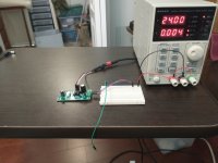
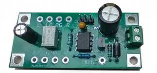
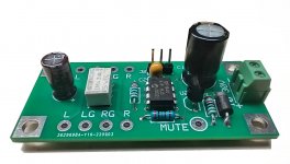
I received the final PCBs and assembled one for testing, photos attached.
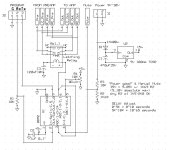
Approximately four seconds after startup, the software reads the power supply voltage level and sets the shutdown/mute voltage at 75% of nominal and activates the output.
In addition, in order to insure that the accuracy of the calibration is not affected by a slow-charging power supply, I added code to measure one more time, this at ten seconds after startup so that any reasonable supply surely will have stabilized.
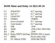
The circuit draws a constant 7mA at 12VDC and 4mA at 24VDC, and surges to 25mA total for about 10 milliseconds only during relay actuation.
Resistor R2 is changed from previous iterations from 2K0 to 1K69 to provide 5-volt headroom at 30 volts. The Picaxe chip is thus theoretically safe up to 35V supply but the approved upper limit remains at 30V. Practical power supply voltage is also limited by the maximum voltages for capacitor C1 and regulator U2.
I believe these changes have addressed all remaining issues. As long as the board is used within the range of 10~30 volts input and if output muting at 75% of normal supply is a good value for the application, this board is precise and works very well.
The Mute feature is activated by connecting the “Mute” pad to the pcb power ground.
Approximately four seconds after startup, the software reads the power supply voltage level and sets the shutdown/mute voltage at 75% of nominal and activates the output.
In addition, in order to insure that the accuracy of the calibration is not affected by a slow-charging power supply, I added code to measure one more time, this at ten seconds after startup so that any reasonable supply surely will have stabilized.
The circuit draws a constant 7mA at 12VDC and 4mA at 24VDC, and surges to 25mA total for about 10 milliseconds only during relay actuation.
Resistor R2 is changed from previous iterations from 2K0 to 1K69 to provide 5-volt headroom at 30 volts. The Picaxe chip is thus theoretically safe up to 35V supply but the approved upper limit remains at 30V. Practical power supply voltage is also limited by the maximum voltages for capacitor C1 and regulator U2.
I believe these changes have addressed all remaining issues. As long as the board is used within the range of 10~30 volts input and if output muting at 75% of normal supply is a good value for the application, this board is precise and works very well.
The Mute feature is activated by connecting the “Mute” pad to the pcb power ground.
Attachments
-
 Mute and Delay 14 Schematic.JPG129 KB · Views: 168
 -
 Mute and Delay 14 PCB Image.JPG212.2 KB · Views: 175
 -
 Mute and Delay 14 - 2.jpg137.5 KB · Views: 173
 -
 Mute and Delay 14 - 1.jpg161.5 KB · Views: 154
 -
Delay and Mute 14 Gerber.zip8.4 KB · Views: 102
-
Delay and Mute 14 08M2 Program.zip1.7 KB · Views: 93
-
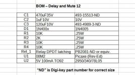
 Mute and Delay 14 BOM.JPG54.7 KB · Views: 161
Last edited:
Nice job. I'm surprised you found a 4 second delay sufficient. I found that I had to wait around 16 seconds for all of the transients to clear.
I prototyped my circuit. Mute is a good idea. I never did add that. I posted this a while back and have since modified the relay circuit so it passes the signal through if the unit is off.
https://www.diyaudio.com/community/threads/b1-with-korg-triode.313612/post-6494692
I prototyped my circuit. Mute is a good idea. I never did add that. I posted this a while back and have since modified the relay circuit so it passes the signal through if the unit is off.
https://www.diyaudio.com/community/threads/b1-with-korg-triode.313612/post-6494692
wapo54001:
This is a little late in asking, but would your design be suitable for power amps as well?
Regards,
Scott
This is a little late in asking, but would your design be suitable for power amps as well?
Regards,
Scott
Possibly a matter of an always-on switching power supply on my unit? Four seconds is just enough.Nice job. I'm surprised you found a 4 second delay sufficient. I found that I had to wait around 16 seconds for all of the transients to clear.
My B1K delay board holds not only the delay/mute relay but also relay-switched input selector. Since my box only has two inputs, one relay does that job. This is an earlier design, not "universal" as is the above circuit, this one is designed for a 24V supply and lacks a little of the sophistication of the smaller board. It fits in the diyaudiostore chassis if you drill new holes for the pcb and move it toward the front an inch. By moving it forward and to the left side I can also fit to the right of the pcb a 24V & +/-15V supply (the +-15 is for my Academy Audio volume control with remote) with PO89ZB filtering on each leg.
Last edited:
Yes, with changes. Off the top of my head I would replace the 2 amp signal relay with a mosfet or opto coupler to drive a 12V/24V relay with any turn-on delay you like. You could quite easily modify the "mute" input or use another pin to sense a speaker output circuit fault and instantaneously disconnect the speaker as well, the delay being dependent only on how fast the physical relay can disconnect. A mosfet would require virtually no current so you would need only one Picaxe pin per mosfet/opto instead of the two I'm using here which doubles the kind of connections you could have so sense both power loss and speaker circuit problems from the same chip.wapo54001:
This is a little late in asking, but would your design be suitable for power amps as well?
Regards,
Scott
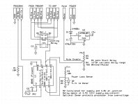
Here is a modification to the old circuit -- the startup delay time will be adjustable with a 10-turn trimmer from zero to 65 seconds. The first five turns will adjust the time with fine resolution from zero to 10 seconds and the second five turns will adjust the delay from 10 to 65 seconds. This will allow everyone to set the delay to their liking without programming the chip.
Here is the proposed PCB and schematic with changes. U1 pin 4 and pin 5 have changed connections, and trimmer resistor R4 has been added. The U1 firmware will need modification, of course, and the addition of R4 to the BOM.
I'm going to verify the circuit before posting the new firmware and BOM. The size of the PCB has not changed.
Attachments

If you're going through the effort, would you consider adding the capability of scaling this design up to work with amplifiers? I'd love to see an alternative to the Store's speaker protection board.
Maybe the better approach would be to design a completely separate board that is focused on that task. The key to this board is the programmability of the chip and I can do that. Also I do quick-and-dirty pcb layouts and get them produced in China for not much money.
The part where I don't have any expertise is in the power amp area. Are you talking about turning power amps ON and OFF, or are you talking about speaker protection? If I have a basic circuit to work with, I can modify it to be controlled from a Picaxe chip, but I don't have the basic circuit or parts requirements. Can you provide those?
The part where I don't have any expertise is in the power amp area. Are you talking about turning power amps ON and OFF, or are you talking about speaker protection? If I have a basic circuit to work with, I can modify it to be controlled from a Picaxe chip, but I don't have the basic circuit or parts requirements. Can you provide those?
I was thinking speaker protection boards, which seem like an extension of your circuit (i.e., adding DC monitoring to turn-on and -off thump protection). Mark Johnson pointed me in the direction of Bob Cordell (Chapter 18.8 of the second revision to his book?) and Rod Elliott (see https://sound-au.com/project33.htm and https://sound-au.com/project208.htm), but I have no expertise in any aspect of circuit design (and very little in basic comprehension), so logically my best recourse is duping someone into figuring out a great circuit for me. Cheeky, no?
I've done more reading. Speaker protection is not a simple extension of my circuit because there is the issue of detecting DC on a circuit that has plenty of AC audio signal. Not so simple, and I'm not the guy to spend a lot of time figuring it out.
Understood. I had no idea but appreciate your taking a look. Thank you for your consideration!
Regards.
Regards.
Hi maybe an antiparallel diode over the relay coil is required for long term reliability. Will the latching relay switch outputs to GND almost instantly at power off?
The latching relay is a 250 ohm coil that limits current flow in both directions to about 20mA at 5V. There is never a 'collapse' situation, only capacitor charge/discharge through the resistance. Although the relay is rated at 5V, the actual 'must switch' voltage is 3.75V @20mA for less than 10 milliseconds, so the real-world logic voltage of 4.5~4.8V at the rated 25mA is more than adequate for the job.
Last edited:
- Home
- Source & Line
- Analog Line Level
- Line Level Delay Relay Circuit