Hi everyone.
I have a Zenith 5k29 that I am recapping and and making into stand alone amp.
on the stereo inputs they have a 2.7meg resistor bridging them.
I didnt have one of that value and replaced it with a 3 meg resistor.
So, is that a suitable replacement?
And what is the purpose of it anyway?
Third should I just wire the line in's direct to the volume pots?
Attachments
The listed tolerance is 10%, so a 3M resistor is just fine. I don't see a ton of purpose to that part, but it may make more sense if we also looked at the reverb unit that could be connected there as well.
Are you turning this into a guitar amp?
Are you turning this into a guitar amp?
there will be no reverb unit. in fact i added new rca input jacks.
this will be for line level stereo input. so no guitar.
this will be for line level stereo input. so no guitar.
I'd be inclined to connect the L and R inputs directly into R1A and R1B and miss out all those pesky sockets on the left.
I would consider them to be redundant when converting this console amp into a stand alone.
I would consider them to be redundant when converting this console amp into a stand alone.

This appears to be an early 'stereo' phono amp from the late 50s or early 60s.
It used matrix addition and or subtraction to get stereo out, and bass low frequency out of a pair of single ended stages plus a matrix output circuit.
The phonograph cartridge was most likely a high impedance Ceramic Cartridge.
The 2.7 Megohm resistor was there to blend some of the right channel into the left channel, and some of the left channel into the right channel.
Yes?
No?
Comments?
This appears to be an early 'stereo' phono amp from the late 50s or early 60s.
It used matrix addition and or subtraction to get stereo out, and bass low frequency out of a pair of single ended stages plus a matrix output circuit.
The phonograph cartridge was most likely a high impedance Ceramic Cartridge.
The 2.7 MΩ resistor was there to blend some of the right channel into the left channel, and some of the left channel into the right channel.
Yes?
No?
Comments?
Maybe. I think rather that the 2.7 MΩ resistor was across L and R in order to provide an equalizing-charge-bleed path to both channels; clearly the
2 MΩ 'loudness' control's value was also chosen not to load the input. I like the thought that this was built for so-called ceramic pickups, actually piezo. They offer pretty good voltages but with very, very high output impedance. High resistor values are a must.
The 3 MΩ is just fine.
⋅-⋅-⋅ Just saying, ⋅-⋅-⋅
⋅-=≡ GoatGuy ✓ ≡=-⋅
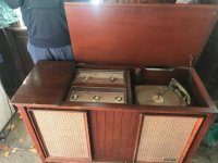
this is similar to what it looked like before i started. the record player was missing pieces and radio didn't work.
the record player plugged into the radio which probably served as preamp and brought up to line before going into the main amplifier which I am rebuilding.
the record player plugged into the radio which probably served as preamp and brought up to line before going into the main amplifier which I am rebuilding.
Attachments
- Home
- Amplifiers
- Tubes / Valves
- line input question