Evening!
I'm trying to do deal with a very reverberant cathedral with 35 meter long ceilings, had the idea of constructing 10-meter high straight-line array from the floor, using full range 2-inch BMA tectonic drivers(tectonic tebm35c10), these drivers have almost perfect horizontal dispersion till 20 kHz, which is desirable here to cover a wide range of the audience,
the goal here is to increase speech intelligibility, music is not of interest and the only important frequency range is from 100 Hz till around 6 kHz, the cabinet is going to be around 5.5 cms wide, and around 5.5 cms center to center, comb filtering shouldn't happen in the frequency range of interest, will probably use an HPF and LPF on everything else to protect the drivers,
In theory and using this formula :d = 1.5 f h2, I'll get a nearfield response from 100 Hz upwards up to 15 meters, which is required in the cathedral to cover the people,
as long as they're in the nearfield of the line arrays, speech intelligibility and clarity should be high, and I'll be losing 3 dB for each doubling of the distance
10 meters of line arrays would equate to around 200 drivers or 100 dB/watt at 1 meter, so I should lose around 10 dB only at the end of the cathedral if using the line arrays next to the alter.
2 of the 10-meter arrays with a very wide horizontal dispersion and limited vertical dispersion provided in the nearfield of the line arrays should be enough to cover it all
is there something wrong theoretically? something that wouldn't work out well in a real-life scenario?
Nothing wrong theoretically. Practically straight line arrays may be beaming too much. I would curve the arrays just like pa systems do.
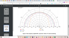
i've attached the off axis and polar responses of the driver i've mentioned, how can the vertical array beam if the drivers are this small, and used in a specific frequency range?
i'd prefer a vertical array cause of aesthetics and other limitations
i'd prefer a vertical array cause of aesthetics and other limitations
Attachments
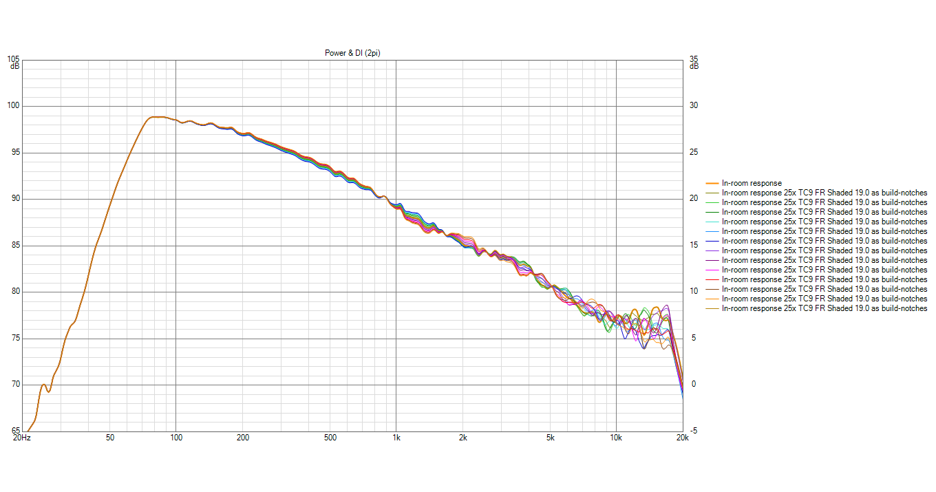
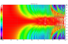
Here's a simulation of a row of 25 drivers (TC9) unshaded (vertical plot):

See how it creates a bundled effect (beam) of roughly +/- 15 degree in the vertical plane?
You can also see the lobes aimed toward the floor and ceiling, which are due to the driver to driver distance. Your driver will be closer together, but also have more dispersion vertically, so it will also show lobing, starting at a higher frequency.
Another thing to account for is the drop of about 3 dB/octave the higher one goes in frequency. You can't simply state it will be 100 dB/watt at 1 meter, as it will show this decline, the higher one goes up in frequency. It needs EQ to bring the top end up/bottom end down.
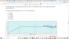
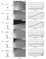
A sample from my frequency shaded array plots (don't have an unshaded variant handy):
This plot shows frequency response at different heights, while having the DSP correction on this array, needed to make only one driver measure flat.
Obviously, the array needs EQ compensation to make it measure flat again.
See the drop the higher one goes from 70 Hz to 10 KHz?
You have tried to make sure you have the nearfield condition out to 15 M. However if the array is on the floor, that reflection will help make it seem taller than it is.
Basically, you have enough information here to put into Vituixcad and run some sims. Add the dispertion graph of that driver into Vituixcad, draw up the line (I don't think it will do 200 drivers though). Make your idea visible to see what would happen and help judge it's viability.
I don't think you'd need that many drivers to cover the top end. The floor will help for the bottom end. A sim could tell you if you can manage a proper area of coverage. Personally, as I've already told you, I'd shade the top end based on the frequency coverage (to limit lobing) and possibly use a horn shape, much like FollGott's CBT
The waveguide will be used to shape the sound where you want it. The vanes will help limit vertical dispersion (lobing) and the waveguide itself helps to limit coverage over the area of interest.
Or... go for a commercial solution like Danley's SBH20 which is a point source with limited vertical coverage, made for jobs like these.

(or one of JBL's CBT solutions, a bend array while being straight to look at. This could be an inspiration to DIY, but it's a multiway array)
See how it creates a bundled effect (beam) of roughly +/- 15 degree in the vertical plane?
You can also see the lobes aimed toward the floor and ceiling, which are due to the driver to driver distance. Your driver will be closer together, but also have more dispersion vertically, so it will also show lobing, starting at a higher frequency.
Another thing to account for is the drop of about 3 dB/octave the higher one goes in frequency. You can't simply state it will be 100 dB/watt at 1 meter, as it will show this decline, the higher one goes up in frequency. It needs EQ to bring the top end up/bottom end down.
A sample from my frequency shaded array plots (don't have an unshaded variant handy):
This plot shows frequency response at different heights, while having the DSP correction on this array, needed to make only one driver measure flat.
Obviously, the array needs EQ compensation to make it measure flat again.
See the drop the higher one goes from 70 Hz to 10 KHz?
You have tried to make sure you have the nearfield condition out to 15 M. However if the array is on the floor, that reflection will help make it seem taller than it is.
Basically, you have enough information here to put into Vituixcad and run some sims. Add the dispertion graph of that driver into Vituixcad, draw up the line (I don't think it will do 200 drivers though). Make your idea visible to see what would happen and help judge it's viability.
I don't think you'd need that many drivers to cover the top end. The floor will help for the bottom end. A sim could tell you if you can manage a proper area of coverage. Personally, as I've already told you, I'd shade the top end based on the frequency coverage (to limit lobing) and possibly use a horn shape, much like FollGott's CBT
The waveguide will be used to shape the sound where you want it. The vanes will help limit vertical dispersion (lobing) and the waveguide itself helps to limit coverage over the area of interest.
Or... go for a commercial solution like Danley's SBH20 which is a point source with limited vertical coverage, made for jobs like these.
(or one of JBL's CBT solutions, a bend array while being straight to look at. This could be an inspiration to DIY, but it's a multiway array)
Attachments
Last edited:
@wesayso excellent help as usual..
is there a basic helpful tutorial that helps me sim this in vituixCad?
about the floor reflection making it taller than it is, how taller exactly? is there a way to calculate that?
I'll definitely look more into the waveguide,
can you tell me more about shading the top end? a lengthier explanation or an example in my case if the frequency range is limited say to 100 hz till 6 khz?
Last edited:
i've attached the off axis and polar responses of the driver i've mentioned, how can the vertical array beam if the drivers are this small, and used in a specific frequency range?
i'd prefer a vertical array cause of aesthetics and other limitations
i was reffering to keele cbt, curved for better coverage
Attachments
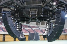
like most of the pa systems
https://apps.spokane.edu/InternetContent/AutoWebs/pamelam/meyer_line_array theory fact myth.pdf
https://apps.spokane.edu/InternetContent/AutoWebs/pamelam/meyer_line_array theory fact myth.pdf
Attachments
straight line array in the room floor to ceiling is something else than line array in large church
In this link: https://www.diyaudio.com/forums/full-range/242171-towers-25-driver-range-line-array-657.html#post6490393 you can find an example of a (frequency) shaded TC9 array that was created to have an even vertical response out to about 6 KHz by using shading. It avoids serious lobes from being created, it was meant to be able cross over to a planar tweeter or something similar.
So the shading was optimized to get an even vertical coverage over as large a bandwidth as possible. Horizontally it will be like the dispersion of a single driver.
About Vituixcad? I just used a basic TC9 array sim from nc535 (I believe he linked it in his thread) and went from there. Learning along the way while I played with it.
There is a driver section where one can upload the driver's off axis angles (as txt files). I believe it has a trace tool to copy/trace the off axis data of a graph like you showed (never used that yet). I haven't seen or read much yet myself, I've been too busy just using it 😱.
The floor (mirror) reflections will help make the array "seem" or "behave" like a taller array, so you 'could' get away with a shorter array. If you use a really tall array, you still need to tailor/steer it to hit/cover your target audience, shading can work as as a means of steering to get the sound where you want it.
Look at the example from Murphy's corner array to get an idea of houw that mirror function works. Yours will work with the floor only, the ceiling will be too far away to help out, another good reason to shade it. It will be a finite array, shading will help to get an even as possible coverage.
Indeed it is. 🙂 I do think he could get away with a straight array that is (frequency) shaded and EQ-ed back into shape. Something like the FollGott waveguide I showed
could help control coverage even more. But it would mean building a prototype to test with the driver of choice. The tebm35c10 isn't very efficient and I can't predict how such a BMR would do in a waveguide.
So the shading was optimized to get an even vertical coverage over as large a bandwidth as possible. Horizontally it will be like the dispersion of a single driver.
About Vituixcad? I just used a basic TC9 array sim from nc535 (I believe he linked it in his thread) and went from there. Learning along the way while I played with it.
There is a driver section where one can upload the driver's off axis angles (as txt files). I believe it has a trace tool to copy/trace the off axis data of a graph like you showed (never used that yet). I haven't seen or read much yet myself, I've been too busy just using it 😱.
The floor (mirror) reflections will help make the array "seem" or "behave" like a taller array, so you 'could' get away with a shorter array. If you use a really tall array, you still need to tailor/steer it to hit/cover your target audience, shading can work as as a means of steering to get the sound where you want it.
Look at the example from Murphy's corner array to get an idea of houw that mirror function works. Yours will work with the floor only, the ceiling will be too far away to help out, another good reason to shade it. It will be a finite array, shading will help to get an even as possible coverage.
straight line array in the room floor to ceiling is something else than line array in large church
Indeed it is. 🙂 I do think he could get away with a straight array that is (frequency) shaded and EQ-ed back into shape. Something like the FollGott waveguide I showed
could help control coverage even more. But it would mean building a prototype to test with the driver of choice. The tebm35c10 isn't very efficient and I can't predict how such a BMR would do in a waveguide.
Last edited:
like most of the pa systems
https://apps.spokane.edu/InternetContent/AutoWebs/pamelam/meyer_line_array theory fact myth.pdf
I'm afraid that's not really doable in my case.. it has to be on the floor not hung from the ceiling, and straight preferably..
like most of the pa systems
https://apps.spokane.edu/InternetContent/AutoWebs/pamelam/meyer_line_array theory fact myth.pdf
In this link: https://www.diyaudio.com/forums/full-range/242171-towers-25-driver-range-line-array-657.html#post6490393 you can find an example of a (frequency) shaded TC9 array that was created to have an even vertical response out to about 6 KHz by using shading. It avoids serious lobes from being created, it was meant to be able cross over to a planar tweeter or something similar.
So the shading was optimized to get an even vertical coverage over as large a bandwidth as possible. Horizontally it will be like the dispersion of a single driver.
About Vituixcad? I just used a basic TC9 array sim from nc535 (I believe he linked it in his thread) and went from there. Learning along the way while I played with it.
There is a driver section where one can upload the driver's off axis angles (as txt files). I believe it has a trace tool to copy/trace the off axis data of a graph like you showed (never used that yet). I haven't seen or read much yet myself, I've been too busy just using it 😱.
The floor (mirror) reflections will help make the array "seem" or "behave" like a taller array, so you 'could' get away with a shorter array. If you use a really tall array, you still need to tailor/steer it to hit/cover your target audience, shading can work as as a means of steering to get the sound where you want it.
Look at the example from Murphy's corner array to get an idea of houw that mirror function works. Yours will work with the floor only, the ceiling will be too far away to help out, another good reason to shade it. It will be a finite array, shading will help to get an even as possible coverage.
the waveguide is a good idea, but I prefer going with the straight array and shade it, it's simpler to build, it looks slim, and will win on the aesthetic side,
I'll try studying more about shading since I have no idea how to apply and what's needed..
I am flexible about choosing a different driver if you think there's something else more suitable for what I'm trying to do
And I've been thinking about another idea, what about using 2-meter arrays in different parts of the cathedral, close to people, would that work better for intelligibility ?
I'm afraid that's not really doable in my case.. it has to be on the floor not hung from the ceiling, and straight preferably..
So the array won't be tilted down towards the listeners? Half the magic sauce of an array comes from it being flown and angled down at the audience, this equalizes the difference in distance between the array and listeners which helps keep the SPL at all listening positions more equal, and utilizes the upper portion of the array to cover the listeners further away.
If the array isn't angled down the portion above about 7ft serves no useful purpose, it just sprays energy on the hard surfaces and exasperates the reverberation problem.
Reverb cannot be combated with speakers, the only fix for that is room treatment.
The use of column speakers is nothing new for this type of space, the cathedral in my home town had 6ft columns along all the side walls that worked reasonably well, I think the system could have been improved with the addition of delay to them but I believe this was installed as a 70v distributed system so a complete rewire would have been necessary.
Instead they opted to install a completely different system hung from the ceiling, from what I gather it works OK but didn't really do anything to address the reverb in the space.. which is no surprise.
in large room, at high frequencies, straight line array will beam like hell, even in the church, no pun intended
with spotty coverage
i have seen bose line arrays in the church, straight, but they were up up one the columns, tilted down
with spotty coverage
i have seen bose line arrays in the church, straight, but they were up up one the columns, tilted down
So the array won't be tilted down towards the listeners? Half the magic sauce of an array comes from it being flown and angled down at the audience, this equalizes the difference in distance between the array and listeners which helps keep the SPL at all listening positions more equal, and utilizes the upper portion of the array to cover the listeners further away.
If the array isn't angled down the portion above about 7ft serves no useful purpose, it just sprays energy on the hard surfaces and exasperates the reverberation problem.
Reverb cannot be combated with speakers, the only fix for that is room treatment.
The use of column speakers is nothing new for this type of space, the cathedral in my home town had 6ft columns along all the sidewalls that worked reasonably well, I think the system could have been improved with the addition of delay to them but I believe this was installed as a 70v distributed system so a complete rewire would have been necessary.
Instead, they opted to install a completely different system hung from the ceiling, from what I gather it works OK but didn't really do anything to address the reverb in the space.. which is no surprise.
the idea behind a longer array than 7ft is to increase the nearfield span of the array, it should fire in a cylindrical way and prevent vertical dispersion and keep a 3db loss by doubling the distance instead of 6db
are you suggesting that this wouldn't work in practice?
Putting the listeners in the nearfield of a speaker should lesser the room effect and make them listen to the speakers instead..
Room treatment is not an option since ALL the cathedral walls and ceilings are covered in an artistic mosaic
i have seen bose line arrays in the church, straight, but they were up up one the columns, tilted down
Did they work??
yes, there were few above each other, each tilted under different angle to enlarge the coverage, you know what I mean
In this post: https://www.diyaudio.com/forums/full-range/337956-range-line-array-wall-corner-placement-55.html#post6205129 nc535 has added a zip file containing a start for a Vituixcad model of a TC9 array.
The driver could easily be substituted, if you have the polar graphs of that driver to be able to use the model in Vituix. It should give you a head start. Follow and read that thread, there have been diagrams posted in it, using different ways of shading.
Playing with a model like that could make what you want to achieve more clear.
I like the idea of using repeating columns, as long as you can include the needed delay for those repeating positions. A few smaller arrays would make more sense to me.
You don't want to blast a lot of energy into a reverberant space. You want to be in control of where you want to send that energy.
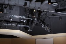
this is what Keele did in the church-like space
Attachments
Last edited:
I like the idea of using repeating columns, as long as you can include the needed delay for those repeating positions. A few smaller arrays would make more sense to me.
You don't want to blast a lot of energy into a reverberant space. You want to be in control of where you want to send that energy.
I love the idea of the JBL vertical CBT's
1 meter long slim array using 2 inch fullrange drivers,
using power tapering to reduce lobing and the beaming of the drivers?
anything more complicated about them i'm failing to see?
And about the waveguides, is there any special consideration to building a 'horn' shape around the to control the horizontal directivity and the separator between the drivers to reduce combing effects?
didn't find helpful detailed information in the follgot build
- Home
- Loudspeakers
- Multi-Way
- line array theory in real life?