It's not in a laboratory!
It looks like I am going to have struggle my way through working it out for myself after all.
It looks like I am going to have struggle my way through working it out for myself after all.
Did you run across these pages from Elliott Sound Products? Some of it is more involved than what you asked about, but maybe there's something of use for you.
Inrush Current Mitigation
https://sound-au.com/articles/inrush.htm
Soft Start Circuits For High Inrush Loads
https://sound-au.com/articles/soft-start.htm
Inrush Current Mitigation
https://sound-au.com/articles/inrush.htm
Soft Start Circuits For High Inrush Loads
https://sound-au.com/articles/soft-start.htm
Hmm, a variac is a piece of laboratory equipment that lets you adjust the AC mains voltage up and down, quite a few percent.
Yet @awkwardbydesign wishes to build an inrush current limiter for a variac, but "it's not in a laboratory". That seems unusual.
Yet @awkwardbydesign wishes to build an inrush current limiter for a variac, but "it's not in a laboratory". That seems unusual.
Lots of people do unusual things for their hobbies. And some have somewhat fixed ideas about how they want to do particular things. Sometimes we can be of more help if we just accept that that's what they want to do. Whether the approach makes sense to anyone else isn't as relevant as whether the thing in question is technically feasible or generally advisable.That seems unusual.
And his handle is awkwardbydesign, so we should probably expect a nonstandard approach 🙂
mattstat; yes I have already looked at the ESP pages. A thermistor with a relay bypass would be my preferred solution, I simply get a headache sometimes with the calculations. Mind you, forums often create bigger headaches!
Mark Johnson; the lab is not the only place for variacs. I have had two 2A variacs for years. First, I used them to reduce 240V to 220V for a pair of Euro spec valve mono blocks, before making bucking transformers for them. Now one is in use to drop the voltage to ~200V for a Lenco L75. Received wisdom claims this is the sweet spot for them, and similar applies to Garrard 301/401s apparently.
rashdow; I already have the variac, and wish to prevent/reduce switch on surge. Nothing more, nothing less.
I am thinking of similar to the top section of Fig.2 here; https://sound-au.com/project224.htm Whether one large or several small thermistors, I don't know.
1500VA you may also want to have a mov for power off. I’ve blown fuses by switching off. A mov across solved the power off back emf spike.
You could use multiple NTPs in series (never in parallel). I use a NTP for multiple torroids in parallel but I switch them in staggered.
You could use multiple NTPs in series (never in parallel). I use a NTP for multiple torroids in parallel but I switch them in staggered.
If you plan to use a relay with a 12V DC coil like Rod Elliott's project 224 Figure 1, Mouser part number 655-T9GV1L14-12 might be a good choice. It's got 30 amp contacts which would probably suffice for a 15A, 230V mains application. Adding a "Quencharc" snubber from Cornell Dubilier would prolong the lifetime of the relay contacts and, as its name implies, suppress contact arcing. But naturally it requires more calculations. Mouser, DigiKey, and Newark (Farnell / Avnet) all sell Quencharcs.
I have three 4PDT 5A relays, so 5A per contact? 3 x 20A, in parallel? If I bought any, I would prefer 230V coils for simplicity, but providing 12V DC isn't really a problem. As I am in the UK, I would buy from Farnell or Rapid, as RS now charge for postage under £30 orders. A
Mr. Johnson, thank you for your excellent advice. I understand this solution and it avoids issues with the NTC being in-circuit 100% of the time. Essentially, it is a manual soft-start circuit with a light bulb as the temporary resistance element. Simple and direct; I like it!For laboratory use: connect a 150 watt incandescent light bulb in series between the mains and the variac. Connect a household SPDT light switch in parallel with the bulb.
Before turn-on: set the SPDT switch to its open circuit ("off") position
At turn-on: apply AC mains to the series assembly. The light bulb glows and limits the inrush current to a value less than or equal to (150W / MainsRMSvoltsge) amperes.
1 second after turn-on: the inrush event is over, the variac's sinusoidal voltage waveform and sinusoidal current waveform are now in their proper phase, so it is now time to close the SPDT switch ("on" position) and short out the light bulb. Now the variac is connected directly to the AC mains.
A pity I'm not in a laboratory. Instead my hifi system is all switched on with one wall switch, to make it wife friendly. And the inrush limiting (and bypass) needs to be automatic, for the same reason. Oh well.
Have you looked at time delay relays for the automatic bypass part? May cost more than rolling your own circuit, but also easier and you can get ones rated for mains voltage use.
And sorry for my rerun - I overlooked the earlier post suggesting the same Elliott pages.
And sorry for my rerun - I overlooked the earlier post suggesting the same Elliott pages.
Tom Christiansen, a member of diyAudio, runs a business called neurochrome.com which sells complete, assembled, tested soft start PCBs. Naturally those soft start boards cost more than DIY soft start projects, since you must pay the cost of (robotic, surface mount) assembly and also testing. Plus he builds, assembles, and tests PCBs in North America, rather than the Far East where costs are lower.
Have a look the neurochrome "Intelligent Soft Start" product and check availability, price, and shipping cost to your door. I think I remember that the ISS is rated for "only" 2000 Volt-Amperes, whereas you need (15A x 230V) = 3450 Volt-Amperes in the worst case. Maybe try the chat/email feature of the neurochrome site to politely inquire about that. . . . maybe you and he might jointly decide that 2000 VA is adequate for your own particular situation (?)
Have a look the neurochrome "Intelligent Soft Start" product and check availability, price, and shipping cost to your door. I think I remember that the ISS is rated for "only" 2000 Volt-Amperes, whereas you need (15A x 230V) = 3450 Volt-Amperes in the worst case. Maybe try the chat/email feature of the neurochrome site to politely inquire about that. . . . maybe you and he might jointly decide that 2000 VA is adequate for your own particular situation (?)
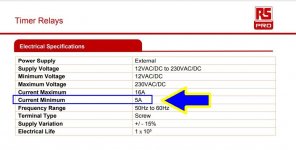
Mattstat: Thanks. Are you referring to this type of thing? https://docs.rs-online.com/ffd7/A700000008881059.pdf
I have been looking at them, but unsure of connections to wiring. And speed of disconnection.
Mark: Cost is a consideration, and importing from USA (or anywhere these days!) adds even more.
I have been looking at them, but unsure of connections to wiring. And speed of disconnection.
Mark: Cost is a consideration, and importing from USA (or anywhere these days!) adds even more.
OK, the delay relay looks OK, just need to calculate the thermistor!
Isn't this where I came in? 😆
Isn't this where I came in? 😆
How does this look? With the varistor between the relay/thermistor and variac for switch-off spikes?

They variac chassis is earthed, not the coil.
They variac chassis is earthed, not the coil.
Yes. There are lots of them from various big name/industrial controls companies. You can usually find something that does whatever you want when it comes to timing, reset states, etc. There are digital and panel mount versions as well.Mattstat: Thanks. Are you referring to this type of thing? https://docs.rs-online.com/ffd7/A700000008881059.pdf
Yeah, sorry about that. With a bypass, the thermistor specifics seem a bit less critical at least. Or you could just use a resistor bank or whatever if you decide that's easier.just need to calculate the thermistor!
Isn't this where I came in? 😆
Seems like a reasonable start.How does this look?
- Home
- General Interest
- Everything Else
- Limiting inrush to a variac.