I am building a preamp and a power amp to amplify a dynamic microphone. The class D power amp chip (TI TPA3130D2) needs it's input limited to an absolute max of 6.3V - otherwise, the chip eventually burns up. 
The preamp is a simple negative feedback TL071 op amp with a gain of 20. The problem is, if you speak too loud into the mic, the output of the preamp is above 6.3Vp-p. TI suggested putting TVS diodes on the preamp output. I haven't put this together yet, but does anyone have a better suggestion?
The preamp is a simple negative feedback TL071 op amp with a gain of 20. The problem is, if you speak too loud into the mic, the output of the preamp is above 6.3Vp-p. TI suggested putting TVS diodes on the preamp output. I haven't put this together yet, but does anyone have a better suggestion?
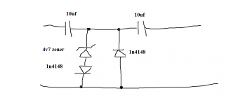
You either clip the signal with diodes (just two 4.7 volt zeners and two 1n4148's is all you need to make a parallel pair) or else look at building an AGC/limiter circuit as used to be found on cassette decks and the like.
I wonder if the 6.3 volts you mention is a point at which a parasitic transistor turns on in the chip causing a destructive latch up.
I wonder if the 6.3 volts you mention is a point at which a parasitic transistor turns on in the chip causing a destructive latch up.
6Vpp is different from 6Vpk, exactly half.
If you are limited to 6V as your maximum input then that usually means 12Vpp = 6Vpk.
Is it possible that Ti mean <6Vac?
If you are limited to 6V as your maximum input then that usually means 12Vpp = 6Vpk.
Is it possible that Ti mean <6Vac?
What about a simple potential divider on the output of the TL071?
If your supply voltage is +/-12V, you need a 3:1 ratio of resistors to get the +/-12V output from the opamp to be +/-3V to the input capacitors of the chip (0 to 6V after the capacitors). You could use 33k at the top and 10k at the bottom. You would of course have less gain.
You can use back to back zeners as Mooly says, but I would put a bit of series resistance before them.
HTH,
Brian
I reread the specs on the chip again - it actually gives the "absolute maximum ratings" as -0.3V to +6.3V. As my input to this amp is the output from my preamp, and my preamp is powered by a single sided supply, my power amp input negative line = ground. So I really only need a zener/TVS diode on the power amp input positive line.
I'll look into the AGC circuits, as I don't want to lower the overall gain, I really want to lower the gain when someone tries to shout into the mic. Guess that might be why someone invented AGC.
Anyone have a simple way to add AGC?
I'll look into the AGC circuits, as I don't want to lower the overall gain, I really want to lower the gain when someone tries to shout into the mic. Guess that might be why someone invented AGC.
Anyone have a simple way to add AGC?
Loads of AGC designs around.
Microphone AGC amplifier
Reading between the lines and I suspect in practice you haven't a real problem. The -0.3 volts will be an absolute and I suspect will be related to what I mentioned earlier, and that is that there will be a parasitic transistor/thyristor that activates (destructively) when this voltage is exceeded.
Latch-up or Latchup
Vague memories of a chip called the LM13600 led me to this discussion, which has links to various circuits. LM13600/13700 compressor SSM/Analog Devices used to make the SSM2120 which was perfect for building a compressor/limiter, but it's discontinued. The THAT 4301 looks like a worthy successor to the SSM2120, though presumably not a drop-in replacement since it has two fewer pins. THAT Corporation 4301 Analog Engine - Dynamics Processor IC Mouser has them in stock for about $10. 4301P20-I THAT | Mouser There's also some on eBay, which is riskier, but possibly preferable to dealing with Mouser.
At least one Yamaha Class D amp chip (YDA148) has several options for AGC and limiting built into the chip; I don't know if they make bigger versions, or if it's feasible to supersize that chip using external drivers and stuff.
At least one Yamaha Class D amp chip (YDA148) has several options for AGC and limiting built into the chip; I don't know if they make bigger versions, or if it's feasible to supersize that chip using external drivers and stuff.
I need to limit the input to the Class D amp - for simplicity I'm going to build this with the TVS diodes I have - they are SMD so I'm going to layup a pcb for the circuit. The AGC circuits I looked at would probably double the size of my preamp board. Since I need to keep the size to a minimum, the TVS diodes would be the smallest board footprint.
This may be a stupid idea, but could you sort of kill 2 birds with one stone by using a diode resistor network to gradually limit the signal ending with a hard limit somewhere?
I'm thinking of something similar to the circuit used in function generators to convert a triangle wave to a sine wave. I used something similar once in a PA system to make a reasonably inaudible limiter, but can't find the schematic at the moment.
Brian.
I'm thinking of something similar to the circuit used in function generators to convert a triangle wave to a sine wave. I used something similar once in a PA system to make a reasonably inaudible limiter, but can't find the schematic at the moment.
Brian.
I'm trying to get a better understanding of the issues and solutions here, and I wanted to pass along something I see.I reread the specs on the chip again - it actually gives the "absolute maximum ratings" as -0.3V to +6.3V. As my input to this amp is the output from my preamp, and my preamp is powered by a single sided supply, my power amp input negative line = ground. So I really only need a zener/TVS diode on the power amp input positive line.
The datasheet does state -0.3 to +6.3 volts limits for the inputs, but it also says the inputs are biased at 3 volts. That would make the limits +3.3V and -3.3V referenced to the 3V input bias (what is called "= ground" in the quote above).
Sofaspud, I'm definitely confused about this.
I have one power supply for both amp circuits and my preamp is a simple single supply op amp biased at Vs/2 with a zener, the output of the op amp feeds into the TPA3130 amp - I do have DC blocking caps on both of the input lines to the 3130 chip.
I posted a question in TI's E2E Community and got a reply "As for your TVS diode question: yes. You need to protect both in the positive and negative direction since audio is AC." I've reposted to the site to get a clarification on how to insert a diode in the GND side of the preamp output/power amp input.😕😕😕
I don't fully understand your power supplies.I have one power supply for both amp circuits and my preamp is a simple single supply op amp biased at Vs/2 with a zener,
The preamp is Vs/2, but what is the power amp supply voltage? Simply Vs?
preamp with TVS diode protection on input to power amp
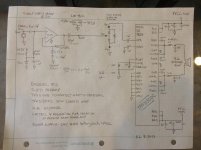
Here's my circuit for the whole shebang. I think the TVS diode (D1213A 6V) is going to protect the input to the TPA3130D2 (class D amp 30W in mono mode) from voltages over 6.3V. I'm going to build this circuit now, but any comments are appreciated!
Here's my circuit for the whole shebang. I think the TVS diode (D1213A 6V) is going to protect the input to the TPA3130D2 (class D amp 30W in mono mode) from voltages over 6.3V. I'm going to build this circuit now, but any comments are appreciated!
Attachments
Mooly - oh yea! I didn't see that before. Thanks for the help.
I'm still not thrilled with it (the diagram I posted) tbh.
One must have a resistor before the limiting diodes.
Hmmm... maybe... the opamp will limit the current safely. I see where your coming from though.
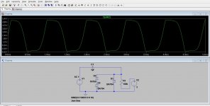
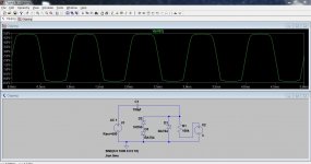
In simulation its not straight forward. With just one coupling cap and the network on the input pin it does work as expected. The resistor is the input to the chip and biased at 3 volts. The input is 6 volts pk with a DC offset of 6 volts to simulate the opamp output voltage (12pk/pk) and clips nicely as shown. Increase the cap and the negative clip points increases to beyond what is physically possible across the diode. Some aspect of the simulation can't be right but I can't just spot it.
Attachments
Last edited:
Some aspect of the simulation can't be right but I can't just spot it.
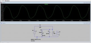
Got it... it's Andrews series resistance 🙂
In simulation the voltage source is ideal (with unlimited current delivery) Add 600 ohm to the impedance of the voltage source and its fine.
Attachments
- Status
- Not open for further replies.
- Home
- Amplifiers
- Solid State
- limiting a preamp output