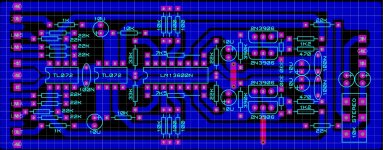
If you look at the layout, power grounds are not separated from signal grounds, there is no rail decoupling, and all the grounds go round in a big circle, giving multiple ways for currents to flow - the perfect definition of "ground loop".
ah ok thank you for your generous reply
Do you have any idea how to fix it or do i have to add some resistor and caps between supply ground and input/signal ground?
Do you have any idea how to fix it or do i have to add some resistor and caps between supply ground and input/signal ground?
Last edited:
Research "star grounding". There's a couple of good threads on here. As for the ICs, I'd add a 10uF to ground for each rail where you enter the PCB, and 0.1uF at each chip, that should give you a good start. You can leave the 0.1uF across the rails, it'll do no harm. Exact values really need to be sorted with a 'scope, checking for ringing and such like, but I suggest will be a decent start.
To fix it would mean redesigning the board. Adding extra components could make things worse. However, a limiter is supposed to add distortion so a little extra hum and noise won't do much harm.
- Status
- Not open for further replies.
- Home
- Amplifiers
- Solid State
- limiter connections