I have some National LH0002CN , the military version, like the HA can which i am using as buffers in a phono preamp and i think i might have connected it the wrong way although not sure about that.The datasheet doesn't specify if the pin asignement is for the top view or the bottom view, so i thought that maybe the National LF356 in the same can that i have a few might tell the right pins.I used the LF356 pin map in the datasheet to connect them in circuit and now the can get hot within 30 seconds...1 minute after power up without doing anything.Truth is that i am supplying them at +-20v which is close to its max +-22v max supply, its measured voltage output in the circuit is identical with its measured input and in my room it's warm, maybe 30 degrees celsius...I can't connect the thing to a turntable and headphones amplifier right now to check if it buzz out anything, but i wondered if anyone would agree that the LH0002 datasheet pin map is the same with the LF356 and it's the bottom view as in the real thing photo.
Attachments
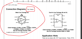


Top view is shown in the data sheet. Notice that the pins go counterclockwise.
They are always numbered CCW as viewed from the top for any package.
They are always numbered CCW as viewed from the top for any package.
Last edited:
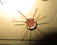
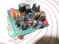
Then it means that the supply voltage is a bit too high for them...or i have to attach a heatsink to them and i already investigated one can's internal guts to see if it's reasonable to do so.Half of the can is filled with thermal resin so it might work well if i use a heatsink.Looking again in the datasheet looks like the idle current might be at max 10ma...but they specify that idle current a 1kohm load while i have 82k ohm DC load to Vcc and nothing to ground...Anyway, i'll try a heatsink.I just hope it's not some weird oscillation there...
Last edited:
And Thank You!Top view is shown in the data sheet. Notice that the pins go counterclockwise.
They are always numbered CCW as viewed from the top for any package.
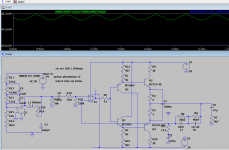
I sim'd the damn thing and it's dissipating about 450mw without doing anything at +-20v so i needed to limit the current through it...
> the damn thing and it's dissipating about 450mw
The datasheet could have told you that. (It could be much more, like 700mW.)
It IS made to run hot. Ten dollar can.
You don't need all that current in audio.
You can add a couple resistors and cut the current in half.
The datasheet could have told you that. (It could be much more, like 700mW.)
It IS made to run hot. Ten dollar can.
You don't need all that current in audio.
You can add a couple resistors and cut the current in half.
Attachments
did that already but q2...q4 collector would better have a 1kohm resistor as the input can take only 300mv max input with a 2k resistor there.With 1k i can go to 350mv max input which is a bit more acceptable for me while with no resistor in the final transitors collector it can take a full 450mv max input with -96...100db thd.For that i will try some heatsinks i borrowed from a scrapped hameg osciloscope :-( .
Attachments
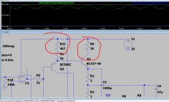
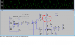
The original design lets the drivers at about half the heat dissipation of the final transistors so i thought that adding the 2k collector resistor would help with thermal compensation, while limiting the max headroom...which i can accept as it's anyway into clipping area, but the purpose was to escape that hard clipping giving me exclusively odd harmonics content.At the same time the op-amp performance won't be affected as it runs at max +-20v so it will be a guitar like drive 🙂.I was thinking lately to use a soft clipping clamping diode pair at the input,| but i need to identify the right diodes that can do that.I saw something like that on Wayne Stegall site...
- Home
- Source & Line
- Analogue Source
- LH0002 pin identification help