The layout matches the schematic. The orientation of C15 and C20 are backwards on the silkscreen. I'm still getting used to designing a layout with a negative rail so I get the orientation reversed often.
The bridge is a 2KBP. Go for a high voltage one. Q4 and Q6 can get warm. They should have heat sink.
Here's what I used for a transformer AS-05T280 - 50VA 280V Transformer - AnTek Products Corp
Hi Jeff,
Sorry, I was looking at the schematic in post 120. Thanks for the heads-up on the two caps. The bridge has staggered legs. Are you just bending the legs or is there a model that has that layout?
Thanks again, Terry
Hi Jeff,
Sorry, I was looking at the schematic in post 120. Thanks for the heads-up on the two caps. The bridge has staggered legs. Are you just bending the legs or is there a model that has that layout?
Thanks again, Terry
Use the schematics in post 35 and 36. Yes you need to bend the legs on the bridge. They're 1" long wire leads normally. 250 volts should have .083" clearance between pads and traces depending on what guidelines you use. It will likely never be an issue until a few years of dust builds up and humidity rises though.
Hi Guys,
I browsed through the thread but can't find it. Are 1/4W resistors good for everything?
Thanks, Terry
I browsed through the thread but can't find it. Are 1/4W resistors good for everything?
Thanks, Terry
Hi Guys,
I browsed through the thread but can't find it. Are 1/4W resistors good for everything?
Thanks, Terry
R21 and R22 are 22R 1 watt. R23 and R24 are 10k 1Watt.
Member
Joined 2009
Paid Member
It's a cool one for those, who want to "hear the tubes". All the voltage gain comes purely from them, with no GNFB "improvements". It will be especially interesting with some class A OPS, like JLH buffer, or even a single-ended one (no cross-over whatsoever)...
OK, some more questions. I'm building the HV power supply. The only transformer I could find in stock is AS-05T320. It has a 320V, 300V and 6.3V windings. I'm hoping that the 300V winding will suffice for this. My question is what changes do I make to the PSU board to work with the 300V winding? Also, same question as above. Which if any resistors need to be over 1/4W?
Thanks, Terry
Thanks, Terry
R7, R8, and R11 are 1 watt. I can't say for sure if the 300 volt transformer will work but that's going to be over 400 volts once it's rectified. That's a lot of voltage to drop.OK, some more questions. I'm building the HV power supply. The only transformer I could find in stock is AS-05T320. It has a 320V, 300V and 6.3V windings. I'm hoping that the 300V winding will suffice for this. My question is what changes do I make to the PSU board to work with the 300V winding? Also, same question as above. Which if any resistors need to be over 1/4W?
Thanks, Terry
Hi Terry,
I have checked the voltages/currents/power parameters with 300V AC (around 420V DC) input voltage - you need to increase R1 from 100K to 160K (PSU schematic from post #36).
It is also important to have Q4 on a small heatsink - dissipation will be around 1.7W (maximum for MJF18004G is 35W on a good heatsink).
Also, make sure C1 is at least 450V rating.
All the rest will work as is.
Cheers,
Valery
Hi Guys,
I was afraid of that. I misread an earlier post about the voltage range and read it as AC when it said DC. I just called Antek and was able to swap out the transformer for the AS-1T230. That should put me back in line.
Another question. Earlier in the thread I think Gareth suggested increasing R7 to a higher value and you seemed to think that was a good idea. Is that still the case. Also, how important is the value of R11? I mainly ask because I don't have any 680R 1W resistors in the bin but I do have other values in stock.
Blessings, Terry
Hi Guys,
I was afraid of that. I misread an earlier post about the voltage range and read it as AC when it said DC. I just called Antek and was able to swap out the transformer for the AS-1T230. That should put me back in line.
Another question. Earlier in the thread I think Gareth suggested increasing R7 to a higher value and you seemed to think that was a good idea. Is that still the case. Also, how important is the value of R11? I mainly ask because I don't have any 680R 1W resistors in the bin but I do have other values in stock.
Blessings, Terry
Hi Terry, you're right - Gareth suggested increasing them for better filtering. You can use, say, 1K for both R7 and R11, or anything between 680R and 1K.
The current through them is roughly 10mA, so difference in voltage drop between 680R and 1K is 3.2 V on each resistor - easy to compensate with the trim pot.
Cheers,
Valery
Hi Valery,
Success, so far. My transformer came in today so I was finally able to test the IPS. The PSU is only able to put out 247Vdc but that seems to be enough. After testing just the tube section with the 247V and 6.3V I hooked up the +-50v transformer and brought it up through my Variac. When I got to about 30V, C15 went up in smoke. That's when I discovered that it was labeled wrong. I reversed it and powered back up everything looks great. I used 10R resistors to tie the outputs to the NFB and I am getting exactly 51mv on each which should mean I have 5.1mA. Should be perfect for the Slewmaster OPS. I played sine and square waves through it and it looks nice. The square waves get a little rounded on the leading edge from about 20khz and up. I will check it again when I get the OPS hooked up. No time for that today so I will get back to you in the morning.
BTW, I built the whole thing on the back side of the PCB except for the IC which had to stay on the silk side. The 22uf 400V caps were a little large so I had to install them on spacers but over all I'm pleased with it. Can't wait to hear it.
Blessings,Terry
Attachments
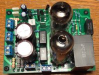
C20 is backwards too.Hi Valery,
Success, so far. My transformer came in today so I was finally able to test the IPS. The PSU is only able to put out 247Vdc but that seems to be enough. After testing just the tube section with the 247V and 6.3V I hooked up the +-50v transformer and brought it up through my Variac. When I got to about 30V, C15 went up in smoke. That's when I discovered that it was labeled wrong. I reversed it and powered back up everything looks great. I used 10R resistors to tie the outputs to the NFB and I am getting exactly 51mv on each which should mean I have 5.1mA. Should be perfect for the Slewmaster OPS. I played sine and square waves through it and it looks nice. The square waves get a little rounded on the leading edge from about 20khz and up. I will check it again when I get the OPS hooked up. No time for that today so I will get back to you in the morning.
BTW, I built the whole thing on the back side of the PCB except for the IC which had to stay on the silk side. The 22uf 400V caps were a little large so I had to install them on spacers but over all I'm pleased with it. Can't wait to hear it.
Blessings,Terry
Hi Jeff,
I just checked and of course you are right. Not sure why it survived the test. Must be low voltage there. I will reverse those too.
Thanks, Terry
I just checked and of course you are right. Not sure why it survived the test. Must be low voltage there. I will reverse those too.
Thanks, Terry
I just swapped them. How did you like this one? Any other issues I should look out for?
Thanks, Terry
Thanks, Terry
Hi Jeff,
I'm sorry. I just looked back through the thread and you already warned me about C15 & C20. I know what you mean about other projects. I have been building the Thermaltrak amp, Apex A33, Krypton C and this one, all at the same time. The Krypton C had been finished for over a week and I haven't had time to clear my bench enough to set up the Slewmaster OPS's, Now that I have this one done I will get them set up. Will be cool to A/B this one against the Krypton C. Hopefully I will hear a noticeable difference.
Blessings, Terry
I'd like to try this input on the TubSoMo output. My Slewmonster is finally sorted out. I just need to finish the chassis on it.
- Status
- Not open for further replies.
- Home
- Amplifiers
- Solid State
- lGl-2, continuing "hybrid madness" - no GNFB class A