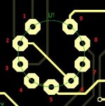
Just in case - looking at the tube from the top (e.g. through the tube), this is the right pins numbering.
There's the problem. I numbered them clockwise from the top view. Looks like I need to mount the boards upside-down.
There's the problem. I numbered them clockwise from the top view. Looks like I need to mount the boards upside-down.
I doubted that 😉
Yeah, the easiest way is to put the tube on the other side of PCB...
It's probably a good thing the heater circuit is floating. 250VDC likely would have been hard on them.
This upside-down board thing is adding a whole new twist to the sport! voltage is pretty close on R3 and R10 when I first flip the board over to measure. I think I'm watching the tube cool. It drifts all over the place when they are upside-down. They quickly settle when right side up.😀
Well, they dissipate some heat, so it's definitely better to keep them looking up, during normal operation.
I've gotten one running. Gain seems low and I seem to be getting 60hz hum as soon as I turn the bias current up. I think it's oscillating on me. I better put these aside until I get my scope fixed up. Tubesomo awaits.
Last edited:
I tried to figure out how I managed to have voltage on the input of these. With the tube installed backwards it looks like the input would have actually been an output. It must have oscillated to actually put out voltage. Did a good job on my scope! Pushing 250V back into the signal generator didn't go well!😱
I tried to figure out how I managed to have voltage on the input of these. With the tube installed backwards it looks like the input would have actually been an output. It must have oscillated to actually put out voltage. Did a good job on my scope! Pushing 250V back into the signal generator didn't go well!😱
Uff... dangerous stuff 😱
Did this amp ever get built and working? I have the boards so I'm interested in seeing what I can do with them.
Thanks, Terry
Thanks, Terry
Did this amp ever get built and working? I have the boards so I'm interested in seeing what I can do with them.
Thanks, Terry
I've assembled a set but never have debugged them yet. The tube layout is backwards so the socket needs to be mounted on the bottom of the board.
Thanks Jeff,
I did see that the tube socket was reversed. I was looking at the board and it looks like most of the parts could just be mounted on the bottom as well. I'm thinking only the IC would have to be mounted on the silk side so that is not a deal breaker. I have only scanned through the thread so far.
I did see that the tube socket was reversed. I was looking at the board and it looks like most of the parts could just be mounted on the bottom as well. I'm thinking only the IC would have to be mounted on the silk side so that is not a deal breaker. I have only scanned through the thread so far.
Hi Jeff,
I've had a little while to look things over. I'm trying to put a Mouser order together and I have some questions.
1) Is there a schematic that matches the part numbers for your layout?
2) On the 250V PSU board, you have a specific layout for the bridge. Do you have a part number for that?
3) How critical is the 250V? Is there a range? What VA is needed?
Thanks, Terry
Hi Terry, I've got a well-working prototype, built with my initial layout, as shown >HERE<. Tubes are at the top side then.
If you've got the boards with Jeff's layout, then the tubes must be placed at the bottom (upside down).
With regards to OPS. This front-end is no-global-feedback, so OPS has to be low-distortion one. The best result is shown with the Hex-FET SlewMonsters - IRFP240/9240 pairs at the output. Warm tube sound 🙂
Regulated PSU is important here (careful with high voltage).
Also note - some capacitors have to be tather high-voltage rated (250-400V).
Cheers,
Valery
Hi Jeff,
I've had a little while to look things over. I'm trying to put a Mouser order together and I have some questions.
1) Is there a schematic that matches the part numbers for your layout?
2) On the 250V PSU board, you have a specific layout for the bridge. Do you have a part number for that?
3) How critical is the 250V? Is there a range? What VA is needed?
Thanks, Terry
The range of the output DC is actualluy 250-300V 🙂
Hi Valery,
Since Jeff was kind enough to share his boards with me I will try to make it work with them. I will probably just flip the boards over and mount everything but the IC on the bottom. I should be able to just rotate the transistors 180 since none of them are thermally coupled. Everything else is just two pin so simple. Only drawback will be the terminals will be reversed from the Slewmaster ops but that is no big deal. I have a 5P Hex-FET Slewmaster OPS sitting here so that should be simple. I have to order some tubes and sockets and a few other items so it will be a week or two before I can get around to building it. I have one of Jeff's cap multiplier boards for the 250v supply so I think I'm good there. What VA does the 250vac transformer need to be?
Thanks, Terry
Hi Valery,
Since Jeff was kind enough to share his boards with me I will try to make it work with them. I will probably just flip the boards over and mount everything but the IC on the bottom. I should be able to just rotate the transistors 180 since none of them are thermally coupled. Everything else is just two pin so simple. Only drawback will be the terminals will be reversed from the Slewmaster ops but that is no big deal. I have a 5P Hex-FET Slewmaster OPS sitting here so that should be simple. I have to order some tubes and sockets and a few other items so it will be a week or two before I can get around to building it. I have one of Jeff's cap multiplier boards for the 250v supply so I think I'm good there. What VA does the 250vac transformer need to be?
Thanks, Terry
No problem, Jeff's boards are nice, we just understood at some point that he's got the tube pins numbered in opposite direction.
Transformer I use is a small 15W toroid, giving both 240V AC (0.05A) and 6.3V AC (1A). Designed for tube guitar pre-amps.
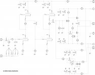
The layout matches the schematic. The orientation of C15 and C20 are backwards on the silkscreen. I'm still getting used to designing a layout with a negative rail so I get the orientation reversed often.
The bridge is a 2KBP. Go for a high voltage one. Q4 and Q6 can get warm. They should have heat sink.
Here's what I used for a transformer AS-05T280 - 50VA 280V Transformer - AnTek Products Corp
The bridge is a 2KBP. Go for a high voltage one. Q4 and Q6 can get warm. They should have heat sink.
Here's what I used for a transformer AS-05T280 - 50VA 280V Transformer - AnTek Products Corp
- Status
- Not open for further replies.
- Home
- Amplifiers
- Solid State
- lGl-2, continuing "hybrid madness" - no GNFB class A