Hi all 🙂
I ordered and received an AMP10BASIC (41Hz Audio:AMP10-BASIC kit) from 41Hz Audio. It arrived in good time, but the forums are STILL down and I can't access the build instructions.
Several emails to the store owner have gone unanswered (but that seems to be the norm having done some searching).
Can anybody help out with instructions? I'm not confident enough to solder it based solely on the schematic.
Many thanks!
Here You go.
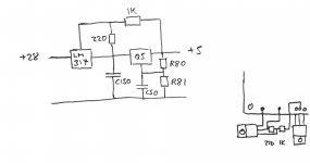
I strongly suggest You modify the 5V according to the included circuit.
Also change c60 to a larger value (I used 470uF) and I recommend You use a input gain of 1.0 (22K for R3, R4, R43 & R44).
Good luck with Your build!
I strongly suggest You modify the 5V according to the included circuit.
Also change c60 to a larger value (I used 470uF) and I recommend You use a input gain of 1.0 (22K for R3, R4, R43 & R44).
Good luck with Your build!
Attachments
You're welcome 🙂
The reason for increasing c60 is to avoid turn-on "pops".
Replacing R100 with the above circuit avoids turn-off "pops" and gives a better regulated 5V.
The reason for increasing c60 is to avoid turn-on "pops".
Replacing R100 with the above circuit avoids turn-off "pops" and gives a better regulated 5V.
Hey xrayspex: do you happen to have the assembly instructions for the regular Amp10 or Amp32 ? REALLY wish I'd copied those from the main page when I bought the amps last year...
Okay, well thanks anyway. The Amp10B ai you sent will give me something to work from for Amp10 so it's certainly better than nothing.
Yeah, I'm starting to wonder if the 41hz site will ever go back online...
Yeah, I'm starting to wonder if the 41hz site will ever go back online...
You use a input gain of 1.0 (22K for R3, R4, R43 & R44)
Alrighty, am almost done with the board stuffing, just a few of the larger caps and 2 resistors to go.
The assembly instructions say 47k for R43 and R44 if using a passive volume pot (which is what I'm doing). However, the kit came with 56k resistors for these locations. Will they still be okay?
Personally I think you should aim for a lower input-gain since this amps input-protection is very sensitive. In my experience -1.0 is perfect even with a passive volume-pot. The chip-manufacturer recommends 20K/20K.
Alright, almost time to power up 🙂
However, there are no polarity indicators on the PCB for the power wiring, nor do the instructions mention it. Any advice?
However, there are no polarity indicators on the PCB for the power wiring, nor do the instructions mention it. Any advice?
There are bridge rectifiers on the board so it's supposed to be powered by AC, and therefore no indication of polarity.
If you want to use DC instead the polarity dosen't matter 🙂
If you want to use DC instead the polarity dosen't matter 🙂
Duh now that I think about it and see how a bridge rectifier works, that makes perfect sense >_<.
What I think I know:
The amp design calls for + and - DC. The rectifier polarities are swapped on the board (i.e. the + pin is ground on one rectifier, and the - on the other one). It is this that creates the + and - DC supplies (which are then filtered by caps). Am I on the right track?
What I think I know:
The amp design calls for + and - DC. The rectifier polarities are swapped on the board (i.e. the + pin is ground on one rectifier, and the - on the other one). It is this that creates the + and - DC supplies (which are then filtered by caps). Am I on the right track?
@xrayspecs Sorry to hi-jack the thread - but re: the Amp10 Basic and the Muting/Relay and the instructions:
I previously modified by Amp10 Basic to follow the altered directions in the PDF - it's possible I did something wrong, but basically with my 18VAC transformer something didn't quite work properly and I ended up spectacularly nuking a TA2022 and melting a few traces off the board (between the bridge rectifier and the big resistor R100 next to the LM317). I managed to replace the TA2022 and repair the traces - and it seems to work - though I'd love to have the speaker muting work properly.
Pic: https://lh5.googleusercontent.com/-...ZRRJDqI/w1125-h844-no/IMG_20130127_202205.jpg - I cut the chip off with side cutters, hence the mess.
Does the modified +5v circuit you've provided totally replace the existing LM317 (which I think is also in your picture?) or work along side it?
Is it discussed anywhere else - I'd love to get some more detail so I can understand what it changes. Should it be done in conjunction with the changes to the time delay resistor R2?
Last edited:
The R2/C60 modification is made to adjust the turn-on delay.
The LM317 (and the 2 resistors) replaces R100 but is used in conjunction (cascade-coupling) with the original regulator. This is done to keep the 5V from collapsing to early during shut-down and thereby producing problems with the turn-off protection.
An added benefit is the better regulated 5V 🙂
Hope this helps.
Interesting! I hadn't seen that set up before - but I see it's actually on the LM317 datasheet as a "tracking pre-regulator" - http://www.diyaudio.com/forums/solid-state/18906-lm317-337-tracking-preregs.html
Thanks!
Thanks!
You're welcome 🙂
Remember that both regs should be mounted (with isolation pads) to some kind of cooling device, case bottom works great.
Remember that both regs should be mounted (with isolation pads) to some kind of cooling device, case bottom works great.
Hello
Does someone have the component layout of the top and bottom of the AMP 10 Basic pcb? And maybe even the BOM? Thanks in advance for your help
Phil
Does someone have the component layout of the top and bottom of the AMP 10 Basic pcb? And maybe even the BOM? Thanks in advance for your help
Phil
- Home
- Amplifiers
- Class D
- LF 41Hz AMP10 Basic assembly instructions