Those 2N5884/6 are better John, but not by much, not much to choose from back then.
I just noticed that there are 4 pairs of outputs so I agree with JC that the new parts
are fine. I'd make sure that if the sockets were repaired that they are making good connections.
I just noticed that there are 4 pairs of outputs so I agree with JC that the new parts
are fine. I'd make sure that if the sockets were repaired that they are making good connections.
Last edited:
Hi John --
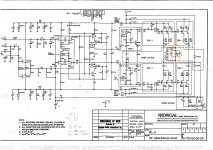
What's the function of this sub-circuit - attached - between the 2 blocks of o/p transistors? Thanks - Phil
That would help to protect the output devices if something upstream went wrong causing (much)
higher than normal bias. It could also be used to allow the drivers to run at a higher bias point for
the same output stage bias. It is a degree of freedom to set each, driver and output at their bias points.
John and Pete -- thanks very much. John, I remember your amp schematic from what was probably Audio Amateur back then. IIRC you used a similar bias circuit in the HCA-3500.
Robert, stick with the devices now in the unit. They are exceptionally qualified for this service, as they have very good safe area at medium voltages, good enough peak current, and only 4MHz f(t), because some newer devices might oscillate in this amp as it is configured. Of course, when the new devices were put in, either the transistor sockets had to be replaced or repaired for the smaller pin diameter of the later devices, but so what?
When the 5684/86 were first developed, I suspect they were made originally for some military project to handle very high current at low voltages, but their rather lousy safe area (second breakdown prone) made them unreliable for more than +/- 25V operation or even less. Mark used these parts because they were so impressive looking, not realizing that they had a lower safe area than the 2N5884/6 that I originally supplied with the JC-3 (the prototype of the ML-2). Big mistake.
Okay clear.
I'll stick with what I got.
Thank you for this design by the way.
Still sounds superb to my (declining) ears...
Here's a picture from an original Motorola JANTX 2N5684.
JAN stands for Joint Army Navy as I recall so it was probably made for military purpose as was a lot of American electronic stuff initially.
http://www.diyaudio.com/forums/attachment.php?attachmentid=592527&stc=1&d=1484599020
Attachments

Bias
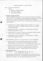
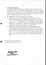
Another thing I noticed when I measured the bias over the .56 Ohm emitterresistors that one resistor gave a lower value 250 mV, and the rest of the seven emitterresistors for the MJ15024/25 was around the 400 mV. I lowered the bias somewhat from the specified .56V to .40V so now the amps draws 300 Watts at idle instead of 400 Watts and the Class A portion is a bit reduced.
According to the servicemanual the deviation between the testpoints should be under the 75 mV which isn't it obviously with the deviation of 150 mV.
http://www.diyaudio.com/forums/atta...nt.php?attachmentid=592823&stc=1&d=1484679854
http://www.diyaudio.com/forums/attachment.php?attachmentid=592830&stc=1&d=1484681967
It is the lower MJ15084 (2N5684 in the schematic) on the NDP-1 driverboard.
The regulatorvoltage is exact in spec: 28 Volts ok all testpoints.
DC is 5.8 mV
When I measure both emitterresistors (amplifier off) they gave the same value.
Should I replace the lower MJ15024 powertransistor on the NDP-1 board?
Any suggestions?
Attachments
So it's supposed to have one amp of bias per transistor pair? So that's what violates the SOA - driving to clipping with no load. That puts full bias current at rail to rail volts. With a typical class b bias those 5684's would hold up fine.
If there is that much discrepancy in bias between parallel devices, don't just change that one. You need to change them all - with units with the same date code or otherwise matched for vbe. One that's really far off from the rest may even be a fake.
If there is that much discrepancy in bias between parallel devices, don't just change that one. You need to change them all - with units with the same date code or otherwise matched for vbe. One that's really far off from the rest may even be a fake.
There's one biaspot on the mainbord that regulates the quiescent current for all the devices but maybe I do not quite catch your drift.So it's supposed to have one amp of bias per transistor pair? So that's what violates the SOA - driving to clipping with no load. That puts full bias current at rail to rail volts. With a typical class b bias those 5684's would hold up fine.
Okay thanks.If there is that much discrepancy in bias between parallel devices, don't just change that one. You need to change them all - with units with the same date code or otherwise matched for vbe. One that's really far off from the rest may even be a fake.
- Status
- Not open for further replies.
- Home
- Amplifiers
- Solid State
- Levinson ML-2 preferred power transistors