I have a Picoscope 5444. For the price I guess it's not bad, but it has some very irritating features. The one nagging me right now is there is no analog input offset adjustment on these!
I am trying to measure ripple and droop on a 96V rail and I must have the input on +-100V/division to capture the signal. This gives me very little analog signal to look at. The zoom feature is purely digital, and even in 14bit mode it is not good enough. On normal scopes I can have the Volt/div at 1V or even less, and just offset the input to -96V and the trace falls in to the center of my screen. Not possible on Picoscopes!
So I need to create an analog input stage that allows me to manually (analogally) adjust the offset prior to the picoscope, and then I can have the volt/div lower.
This must be a common problem with those using sound cards as scopes?
I am building a diff-amp with level shift right now, but perhaps anyone here has a better tried-out circuit?
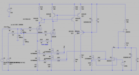
The circuit is not finished and does not show input protection, offset adjustment, or finished values etc. But the idea is a simple diff input with mirrors to place the output signal near ground potential. The diff input pair will be connected near same potentials, say on each side of small resistance on the voltage rail. I figure max 10Vp differentially on the input. The inputs can handle ca 10-200V common mode.
I am trying to measure ripple and droop on a 96V rail and I must have the input on +-100V/division to capture the signal. This gives me very little analog signal to look at. The zoom feature is purely digital, and even in 14bit mode it is not good enough. On normal scopes I can have the Volt/div at 1V or even less, and just offset the input to -96V and the trace falls in to the center of my screen. Not possible on Picoscopes!
So I need to create an analog input stage that allows me to manually (analogally) adjust the offset prior to the picoscope, and then I can have the volt/div lower.
This must be a common problem with those using sound cards as scopes?
I am building a diff-amp with level shift right now, but perhaps anyone here has a better tried-out circuit?
The circuit is not finished and does not show input protection, offset adjustment, or finished values etc. But the idea is a simple diff input with mirrors to place the output signal near ground potential. The diff input pair will be connected near same potentials, say on each side of small resistance on the voltage rail. I figure max 10Vp differentially on the input. The inputs can handle ca 10-200V common mode.
Attachments
Do you just need to remove the DC component? A capacitor in series (of an adequate voltage rating) will do that for you.
I may be confused but it seems you have the scope at 100V/div so the max would be at least +/- 400V. I would look for a 50V/div first.
I have a Tek 7A13 which can measure as you would like but its capabilities are far from common in analog scopes. Normally you would use divide by 10 or divide by 100 probes and if you are measuring current through a resistor at high voltage do it with a differential measurement. You would not need the dynamic range of a 7A13 to do that. Also for DC a DVM is much better for measuring drop under load.
Never the less if you do build the circuit it would be interesting to see what you get in frequency response and DC drift. This is the older Tek version differential amp: 1A5 - TekWiki its still quite a complex beast.
No I need DC response to capture the current as well.
I don't get it. You need to measure a DC voltage to capture the current?
Edit: I just read 1audio's response, he assumes you are measuring on both sides of a current sense resistor. If that is the case, would it be possible to put the sense resistor in the ground wire instead? Or otherwise use a multimeter to measure the average drop and an AC-coupled two-channel scope to see the waveform?
Last edited:
Hi, I know the volt/div is confusing the way I wrote it. But that is how Picoscope writes it. The 'V/div' is actually full screen voltage range on a picoscope, for instance selecting 5V/div means the max and min range on the screen is +5 and -5V. They have some weird ways of presenting data.I may be confused but it seems you have the scope at 100V/div so the max would be at least +/- 400V. I would look for a 50V/div first.
I have a Tek 7A13 which can measure as you would like but its capabilities are far from common in analog scopes. Normally you would use divide by 10 or divide by 100 probes and if you are measuring current through a resistor at high voltage do it with a differential measurement. You would not need the dynamic range of a 7A13 to do that. Also for DC a DVM is much better for measuring drop under load.
Never the less if you do build the circuit it would be interesting to see what you get in frequency response and DC drift. This is the older Tek version differential amp: 1A5 - TekWiki its still quite a complex beast.
At the moment my challenge is related to measurements on the HV-rail, but in general I just need a circuit that gives me analog offset capability b/c there are many times that is necessary.
I think maybe a smarter way is to simply voltage divide the input wildly, say 100:1 or more, and then have a circuit gaining it up again but with offset adjustments. The high bandwidth scopes we get today most likely use opamps running with low voltage rails, maybe max 3V. I can't see how else they get such amazing bandwidths.
Yes DC drift and freq response will probably be the hardest to get decent in any circuit I come up with.
Smartest would be finding a Tek diffamp you mentioned, and use it as a head pre in front of the Picoscope. Damn, why did I get a picoscope!?
Can the firmware be hacked to provide this capability? Although I'm still not sure its purpose. You could use AC couping and measure DC with a meter, I you really need to.
Hi, I know the volt/div is confusing the way I wrote it. But that is how Picoscope writes it. The 'V/div' is actually full screen voltage range on a picoscope, for instance selecting 5V/div means the max and min range on the screen is +5 and -5V. They have some weird ways of presenting data.
At the moment my challenge is related to measurements on the HV-rail, but in general I just need a circuit that gives me analog offset capability b/c there are many times that is necessary.
I think maybe a smarter way is to simply voltage divide the input wildly, say 100:1 or more, and then have a circuit gaining it up again but with offset adjustments. The high bandwidth scopes we get today most likely use opamps running with low voltage rails, maybe max 3V. I can't see how else they get such amazing bandwidths.
Yes DC drift and freq response will probably be the hardest to get decent in any circuit I come up with.
Smartest would be finding a Tek diffamp you mentioned, and use it as a head pre in front of the Picoscope. Damn, why did I get a picoscope!?
That explanation helps. I have been using Picoscopes for 20 years now and they still seem to have the best software (and still flawed).
Yes- a max of 10V in and its a manageable project. The HV would be challenging and drift prone.
One of my future projects is a box (or really a PCB w/ edge connector) to enable powering and connecting a Tek 7K plugin to a digital scope. It actually looks pretty simple with today's super opamps. Maybe not GHz but 100 MHz is attainable and that's enough for any of the unique plugins.
- Home
- Design & Build
- Equipment & Tools
- Level shifting (input offset) input circuit.