Let me give a simple example.
Used to describe PWM amplifier. Ordinary analog amplifier. And the principle of class a amplifier.
For example, we need to design a regulated power supply (the amplifier is actually a regulated power supply)
For example, we need to stabilize the DC voltage of 30V to obtain 12V DC voltage. No matter how 30V changes, or it will become 31 or 28V in a moment. But the output DC 12V voltage will never change.
Then we have two plans.
1. Use PWM regulated power supply. That is, PSU. Get 12V voltage. This is the same principle as class D.
2: Use LM317 regulated power supply to obtain 12V voltage. This is the principle of traditional analog amplifier.
3: If LM317 plus constant current source is used. Get 12V voltage. But it keeps its current at maximum. This is the principle of class A.
In fact, we can draw a conclusion through this principle.
No matter it is a good place. Or worse. We can all understand it easily.
For example, PWM will save power. But its output signal is worse than LM317. There is no purity of LM317 power quality. When the current fluctuates greatly. PWM may cause the output 12V voltage to drop more.
However, LM317 will have a high voltage difference. So it will generate relatively large amount of heat. Of course, this is related to the output current. The voltage is also related to the input voltage minus the output voltage.
So it's actually easy for us to judge. What are we doing. What kind of products are needed.
But many people don't understand this.
If the output voltage is very low. electric current. Then I think LM317 will be better for this regulated power supply.
If high current output is required for a long time. And it is not particularly sensitive to the voltage fluctuation of the output.
Such as TV. Charger. I think it would be better to use PWM power supply.
PWM= CLASS D。 Lm317= linear amplifier, CLASS AB. LM317+Current constant load= CLASSA
In fact, PSU and class d have exactly the same structure. For example, TL494 can also make class D. Or irs2092s can also be made as PWM regulated power supply.
The voltage stabilizing IC and class AB also have the same structure. For example, LM317 can be designed as a class AB class a amplifier. Or lm3886 can also be made as a linear regulated power supply.
It's just that the output signal is selected differently.
For example, we use TL494. Let him output the audio signal. Then the PWM regulated power supply will become a class D amplifier.
Or we use lm3886t, and the power supply voltage is + -40v. We let him output a fixed DC voltage, such as 20V DC. Then lm3886 will become a linear regulated power supply.
Attachments
Interesting and enlightening. I started out building my first class D amplifiers using your Lx modules - primarily the L20. Easy modules to work with, and I powered them with both linear and SMPS supplies.
What you said should be l20d?.Interesting and enlightening. I started out building my first class D amplifiers using your Lx modules - primarily the L20. Easy modules to work with, and I powered them with both linear and SMPS supplies.
In fact, lm3886 is widely used in motor DC drive amplifier circuit.
Output a fixed regulated, DC voltage. It is used in industrial DC regulated power supply. It has a high current output. And it's easy to design.
Because the application of lm3886 is not limited to audio amplification. Including industrial applications. The demand is very large. So lm3886 is very expensive now. Because the demand is too large. Cause chip shortage.
Class-D amplifiers
Since the first edition of this book, Class-D amplifiers have increased enormously in popularity. This is because Class-D gives the highest efficiency
of any of the amplifier classes, although the performance, particularly in
terms of linearity, is not so good. The rapid rate of innovation means that
this section of the book is much more of a snapshot of a fast-moving scene
than the rest of the material. I do not want to keep repeating ‘At the time of
writing’ as each example is introduced, so I hope you will take that as read
The history of the Class-D amplifier goes back, as is so often the case
with technology, further back than you might think. The principle is generally regarded as having surfaced in the 1950s, but the combination of
high switching frequencies and valve output transformers probably did not
appear enticing. The first public appearance of Class-D in the UK was the
Sinclair X-10, which claimed an output of 10 W. This was followed by
the X20, alleging a more ambitious 20 W. I resurrected one of the latter in
1976, when my example proved to yield about 3 W into 8. The THD was
about 5% and the rudimentary output filter did very little to keep the low
switching frequency out of the load. The biggest problem of the technology
at that time was that bipolar transistors of suitable power-handling capacity
were too slow for the switching frequencies required; this caused serious
losses that undermined the whole point of Class-D, and also produced
unappealingly high levels of distortion. It was not until power FETs, with
their very fast switching times, appeared that Class-D began to become a
really practical proposition
Amplifiers working in Class-D differ radically from the more familiar Classes
of A, B and G. In Class-D there are no output devices operating in the linear
mode. Instead they are switched on and off at an ultrasonic frequency,
the output being connected alternately to each supply rail. When the
mark-space ratio of the input signal is varied, the average output voltage
varies with it, the averaging being done by a low-pass output filter, or by
the loudspeaker inductance alone. Note that the output is also directly
proportional to the supply voltage; there is no inherent supply rejection at
all with this sort of output stage, unlike the Class-B output stage. The use
of negative feedback helps with this. The switching frequencies used range
from 50 kHz to 1 MHz. A higher frequency makes the output filter simpler
and smaller, but tends to increase switching losses and distortion.
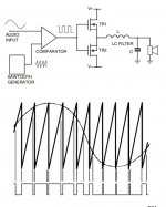
The classic method of generating the drive signal is to use a differential comparator. One input is driven by the incoming audio signal, and
the other by a sawtooth waveform at the required switching frequency.
A basic Class-D amplifier is shown in Figure 11.1, and the PWM process
is illustrated in Figure 11.2.
Clearly the sawtooth needs to be linear (i.e., with constant slope) to prevent
distortion being introduced at this stage. There are other ways to create the
required waveform, such as a sigma-delta modulator
Since the first edition of this book, Class-D amplifiers have increased enormously in popularity. This is because Class-D gives the highest efficiency
of any of the amplifier classes, although the performance, particularly in
terms of linearity, is not so good. The rapid rate of innovation means that
this section of the book is much more of a snapshot of a fast-moving scene
than the rest of the material. I do not want to keep repeating ‘At the time of
writing’ as each example is introduced, so I hope you will take that as read
The history of the Class-D amplifier goes back, as is so often the case
with technology, further back than you might think. The principle is generally regarded as having surfaced in the 1950s, but the combination of
high switching frequencies and valve output transformers probably did not
appear enticing. The first public appearance of Class-D in the UK was the
Sinclair X-10, which claimed an output of 10 W. This was followed by
the X20, alleging a more ambitious 20 W. I resurrected one of the latter in
1976, when my example proved to yield about 3 W into 8. The THD was
about 5% and the rudimentary output filter did very little to keep the low
switching frequency out of the load. The biggest problem of the technology
at that time was that bipolar transistors of suitable power-handling capacity
were too slow for the switching frequencies required; this caused serious
losses that undermined the whole point of Class-D, and also produced
unappealingly high levels of distortion. It was not until power FETs, with
their very fast switching times, appeared that Class-D began to become a
really practical proposition
Amplifiers working in Class-D differ radically from the more familiar Classes
of A, B and G. In Class-D there are no output devices operating in the linear
mode. Instead they are switched on and off at an ultrasonic frequency,
the output being connected alternately to each supply rail. When the
mark-space ratio of the input signal is varied, the average output voltage
varies with it, the averaging being done by a low-pass output filter, or by
the loudspeaker inductance alone. Note that the output is also directly
proportional to the supply voltage; there is no inherent supply rejection at
all with this sort of output stage, unlike the Class-B output stage. The use
of negative feedback helps with this. The switching frequencies used range
from 50 kHz to 1 MHz. A higher frequency makes the output filter simpler
and smaller, but tends to increase switching losses and distortion.
The classic method of generating the drive signal is to use a differential comparator. One input is driven by the incoming audio signal, and
the other by a sawtooth waveform at the required switching frequency.
A basic Class-D amplifier is shown in Figure 11.1, and the PWM process
is illustrated in Figure 11.2.
Clearly the sawtooth needs to be linear (i.e., with constant slope) to prevent
distortion being introduced at this stage. There are other ways to create the
required waveform, such as a sigma-delta modulator