just got the t2020+..
i read the last 10 pages for at least 10 times already..
order the capacitors according to XtremeRevolution.
any recommendations for the op amp??
whats the differences between changing them and bypassing them?
if bypassing, is it bypassing 1 or both of them??
if changing, what is a good choice??
Hello
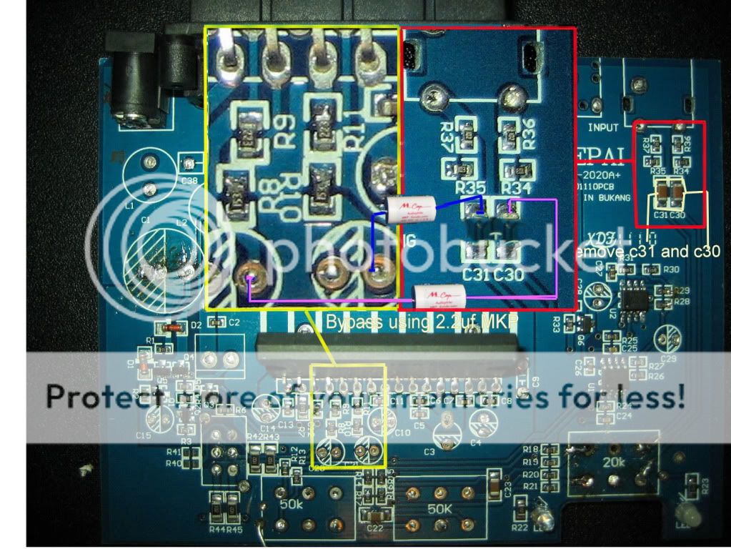
By doing the bypass I posted for the ta2020a+ you are disconnecting the input signal from the tone, volume control and two op amps.
You are essentially comming from the input then r36, r37,r35 ,r34 to coupling cap then r8, r10, r9, r11 to IC TA2020 pins 9, 10, 11, 13.
As you can see on the pic of my post I even removed the caps from the op amps circuit. That means op amps have no power and are just sitting there, not being feed and not connected.
I think you can and must use 2.2uf mkp instead of electrolytic 1.75uf,
I have had only used the 1.75uf because I don't have 2.2uf caps right now. If you want your lepai to be more like the tripath suggested circuit you can also replace the resitors on r37,r36, r35, r34, r8, r10, r9, r11 and them go to the inductors, output caps etc.
[]'s
I just bought a new one for mine on ebay, 5.5USD shipped to finland.
Link: IC TRIPATH ZIP-32 TA2020 TA2020-020 | eBay
You have to message the seller that you want the ta2020-020 specifically.
Mine died from "trying how loud I could go" 🙂 Before it had just clicked off and clicked back on when the volume was at a sane level but this time it didn't 🙁
Link: IC TRIPATH ZIP-32 TA2020 TA2020-020 | eBay
You have to message the seller that you want the ta2020-020 specifically.
Mine died from "trying how loud I could go" 🙂 Before it had just clicked off and clicked back on when the volume was at a sane level but this time it didn't 🙁
Bellow I edited the tripath schem. The values in red are not confirmed and are based on what is printed on the TA2020a+ components.
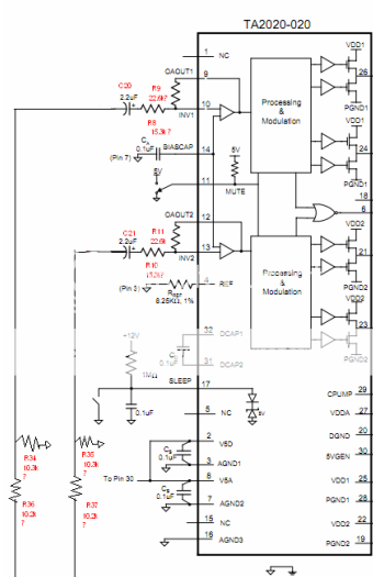
http://www.e-ele.net/DataSheet/TA2020.pdf
http://www.e-ele.net/DataSheet/TA2020.pdf
Any Idea How to check whether the chip is still alive or not ? simple method will be fine.. Thanks
This seems like a questionable statement. Removing the capacitors does not remove the power from the op amps.As you can see on the pic of my post I even removed the caps from the op amps circuit. That means op amps have no power and are just sitting there, not being feed and not connected.
Confirm that the TA2020 chip is getting power, confirm it isn't in mute or sleep mode, inject an audio signal to the left then right inputs.Any Idea How to check whether the chip is still alive or not ? simple method will be fine.. Thanks
The inputs at the chip, not at the back of the unit.
Last edited:
This seems like a questionable statement. Removing the capacitors does not remove the power from the op amps.
Hello
I'm just a noob here and i'm trying to find awsners to the questions concerning the TA2020A+. Questions that have been already asked many times but not answered . I think bypass =no signal + no caps=no power
That way I would appreciate if you could point out exactly were from is this power/signal comming from ?
[]'s
Last edited:
...
I think you can and must use 2.2uf mkp instead of electrolytic 1.75uf,
I have had only used the 1.75uf because I don't have 2.2uf caps right now. If you want your lepai to be more like the tripath suggested circuit you can also replace the resitors on r37,r36, r35, r34, r8, r10, r9, r11 and them go to the inductors, output caps etc.
[]'s
2.2 uF, really? That is what Tripath recommended?
Good to know. I put the original electrolytics back so I could close the box, but I retained your bypass. I will try to get some better caps on my next parts order.
Thanks.
While waiting for the parts to arrive to my own TA2020-based design I just ordered a Lepai to use as reference.
Anybody knows how to add the OVERLOADB indicator? In the datasheet appears this:
Overload
The OVERLOADB pin is a 5V logic output. When low, it indicates that the level of the input signal has overloaded the amplifier resulting in increased distortion at the output. The OVERLOADB signal can be used to control a distortion indicator light or LED through a simple buffer circuit.
What kind of buffer circuit does it refer to?
2.2 uF, really? That is what Tripath recommended?
Good to know. I put the original electrolytics back so I could close the box, but I retained your bypass. I will try to get some better caps on my next parts order.
Thanks.
Yes, 2.2uf.
I purchased mundorf 2.2uf mcaps 400v 3% that I hope to be delivered sometime during next week along with tk2050 boards.
Replying to your previous post I think the TA2020A signal goes to vol> op amp1>tone controls > op amp2 > ta2020 pins 9, 10, 12 ,12. From there the schematic is pretty much the same on all the versions.
http://www.e-ele.net/DataSheet/TA2020.pdf
Good luck to all of us
Last edited:
Anybody knows how to add the OVERLOADB indicator? In the datasheet appears this:
Overload
The OVERLOADB pin is a 5V logic output. When low, it indicates that the level of the input signal has overloaded the amplifier resulting in increased distortion at the output. The OVERLOADB signal can be used to control a distortion indicator light or LED through a simple buffer circuit.
What kind of buffer circuit does it refer to?
A transistor as a buffer.
But I think a good LED will be able to drive directly:
+5V --->------[5k ohm]----->------[LED]---->----OVERLOADB
Regarding the 2020 chip..
Is it considered as a easy to burn amp IC?
How does it compares to other amp IC's in terms of durability? (LA, TDA, STK etc..)
Is it considered as a easy to burn amp IC?
How does it compares to other amp IC's in terms of durability? (LA, TDA, STK etc..)
Running a jumper wire from the input caps to the TA2020 bypasses the volume control, op amps, and tone control. And so there is no audio signal for the op amps to act upon. But removing the caps still leaves power supply voltage to the op amps - there is power being consumed by the op amps. Cutting the traces for pins 4 & 8 of the op amps removes all power.Hello
I'm just a noob here and i'm trying to find awsners to the questions concerning the TA2020A+. Questions that have been already asked many times but not answered . I think bypass =no signal + no caps=no power
That way I would appreciate if you could point out exactly were from is this power/signal comming from ?
A transistor as a buffer.
But I think a good LED will be able to drive directly:
+5V --->------[5k ohm]----->------[LED]---->----OVERLOADB
Yes, that is what I was thinking… but maybe driving it directly damages the chip. I will have to investigate about the transistor option.
Any Idea How to check whether the chip is still alive or not ? simple method will be fine.. Thanks
This is what happened to me... there was a short circuit after the op-amp modification .. there after the amp stop responding ..While checking the amp IC using multi-meter there was another elctric shortage between ic pins..After all this drama, the blue LED started to dim 😕..After inspection we decided there is a electrical short inside the circuit.. (standby current is way over 1 AMP)..now waiting for new ta2020..
What do you think?? your ideas highly appreciated..
Running a jumper wire from the input caps to the TA2020 bypasses the volume control, op amps, and tone control. And so there is no audio signal for the op amps to act upon. But removing the caps still leaves power supply voltage to the op amps - there is power being consumed by the op amps. Cutting the traces for pins 4 & 8 of the op amps removes all power.
You are right. But I might unsolder op amps and preserve the pcb for future mods, who knows.
Thank you for the awsner.
Hello
By doing the bypass I posted for the ta2020a+ you are disconnecting the input signal from the tone, volume control and two op amps.
You are essentially comming from the input then r36, r37,r35 ,r34 to coupling cap then r8, r10, r9, r11 to IC TA2020 pins 9, 10, 11, 13.
As you can see on the pic of my post I even removed the caps from the op amps circuit. That means op amps have no power and are just sitting there, not being feed and not connected.
I think you can and must use 2.2uf mkp instead of electrolytic 1.75uf,
I have had only used the 1.75uf because I don't have 2.2uf caps right now. If you want your lepai to be more like the tripath suggested circuit you can also replace the resitors on r37,r36, r35, r34, r8, r10, r9, r11 and them go to the inductors, output caps etc.
[]'s
as per what u mention in the previous post, are the polarity of c20 and c21 printed wrongly?? so i should go opposite when putting in new caps for c20 and c21??
i tried to change a 2.2uf cap on c20 and c21 following the polarity of the printings.. indeed it sounds better and i notice higher clarity of the output..
but on the highs, i got distortion on one side of the speakers..
i change back the 1.75 uf caps and the distortion disappear..
Yes, you should connect it to the positive on the PCB for the best using bipolar 2.2uf MPK's .
You got distortion even at low volume ? If it happens only when you go up with the power that may be your speaker wires that are fault.
I replaced inductors and that was the best mod so far, improved all aspects of the SQ. I am addicted to this thing cause I can't wait to give it another try.
An externally hosted image should be here but it was not working when we last tested it.
[]'s
Last edited:
I would like to buy a Lepai Lp-2020a+ from this ebay shop "earphones_uk". I wondered if anyone else has tried one from him and checked that the board is the 2020a+ and not the 2020B in the wrong box!
Regards
Chris
Regards
Chris
I replaced inductors and that was the best mod so far, improved all aspects of the SQ. I am addicted to this thing cause I can't wait to give it another try.
[]'s
care to share what inductors you replaced with and how u replaced them??
- Status
- Not open for further replies.
- Home
- Amplifiers
- Class D
- Lepai T-Amp with TA2020