I recieved myNE5532's but i got the wrong ones! Duh! Im such a noob and didnt take any notice of the "dip 8" written on the listing
can i still solder these to the board but using wires to connect each leg or is it just not worth it?
Unbelievable! I did the exact same thing.. Apparently the pinout is the same so it's possible, but I guess it will be pretty hard..
Anyway, I ordered a lepai lp2020a+ for 21$ shipped on ebay, and I'll be getting it in a few days. I will probably mod it to death 🙄
I'll be back on here asking silly questions in a few days 😉
Hi everybody!
First of I have to thank you all for contributing all this amazing information on this forum!
I just registered an account here on DIY Audio, but I have been following this forum thread for a few years now, and now i finally have made my own portable stereo with this fantastic Lepai TA2020A+ and a 7,2Ah accumulator.
I am really satisfied with the result and I have been able to play constant for over 5 hours.
My really big concern was the power-cable and the power-connectors, but i solved that with a broken power-adapter from an old laptop (only the cable from the power-adapter).
I tested it and found out that the + was in the middle and the - was on the outside of the connector. I also put a 10A fuse on the +cable just in case and put cable shoes on the cables to ensure a simple way to connect them to the battery poles.
I use a aluminumcase from our local hardware store to put all the stuff in and i put two 4" full range speakers on one side.
When i have found out how to post images here i will do so.
Until then i will post a few links with the images here for you to see =)
Picture one (inside the case):
http://www.festivalstereo.se/images/img_20111011_013201.png
Picture two (front of the case):
http://www.festivalstereo.se/images/img_20111011_012504.png
Picture three (Lepai TA2020A+ connected to battery with my home made cable):
http://www.festivalstereo.se/images/img_20111011_014013.png
Picture four (My home made power-cable with a fuse holder)
http://www.festivalstereo.se/images/img_20111011_013845.png
I hope its not to early for me to post links, this is only to show my pictures, not as useless spam.
Cheers to all on this forum, you have given me a lot of useful information to get through with my home made stereo!
// Mogar123 from Sweden
Ive made a huge mistake and connected the wire to my battery the wrong way round and now it all seems to work like normal except it does not output any sound and also does not click when switched on like it used to.
Any idea what it could be or what I should test? Could it be the replay/large black component with 12v written on it?
I have started a thread for it here
I hope someone can bring it back to life as ive just purchased a battery and was all ready to make my boombox doh!
Any idea what it could be or what I should test? Could it be the replay/large black component with 12v written on it?
I have started a thread for it here
I hope someone can bring it back to life as ive just purchased a battery and was all ready to make my boombox doh!
Ok I just got one without power adapter and going to use it with my PC. And Im going to get power from my PC power supply 12V rails 🙂
And In future im going to buy another and use it on my Bus. It got 2*12V 120ah Batteries and im going to tap a wire and get power from one battery. My concern is since the battery power is high (120Ah) will it be a problem for AMP?
Thanks
And In future im going to buy another and use it on my Bus. It got 2*12V 120ah Batteries and im going to tap a wire and get power from one battery. My concern is since the battery power is high (120Ah) will it be a problem for AMP?
Thanks
I got another one off ebay arrived a few days ago. Its an LP-2020A+ on the case, but the board inside is LP-2020B... It has the 'protection relay', surface mount components but only one op-amp. I mapped out the relay protect circuit, but I'm not convinced by it... Its still connected to the fault pin and looks like it will toggle the relay off if this goes high, but it is also connected to the mute/over voltage circuit. This will perform an automatic reset of the fault condition (see datasheet), which I don't think is desireable. Another thing - the relay only switches one side of each differential output - so for example, a short could occur on either pin and will not necessarily be disconnected by the relay. I'm not sure why this relay protect is necessary other than to prevent the switch on pop - but then why connect to the fault pin? From the tripath data sheet:
"The TA2020-020 is guarded against over-temperature and over-current conditions. When the device goes into an over-temperature or over-current state, the FAULT pin goes to a logic HIGH state indicating a fault condition. When this occurs, the amplifier is muted, all outputs are TRI-STATED, and will float to 1/2 of VDD."
What do other people think of this 'relay protect'? If I get time I'll draw up the schematic I have and post.
I've made the following mods to the new one:
1. Removed overvoltage circuit and relay circuit - tied mute to gound and added an LED to the fault pin.
2. Removed tone control/volume control and op-amp
4. Replace input caps with 2.2 uF (they were 1.75uF)
I'm very pleased with the result - it does sound much better without the tone controls as an earlier post suggested - better bass response, and I think the treble sounds sharper too. Using a 12V regulated power supply I don't need the protection circuit, or the extra diode on the output (data sheet says they are only needed for voltages >13.5V). The switch on 'thump' is minimal once the op-amp/tone control is removed, as an earlier post suggested.
Hi all,
I have the same Lepai as padgettr. It's has LP-2020A+ on the case, but the board inside says LP-2020B. It has the protection relay and some surface mount components, but only one op-amp.
Candoumi previously linked to the photo of the board:
Lepai LP-2020A+ - My Photo Gallery
I made a few mods the amp, and now it sure sounds better to my ears... cleaner, faster, more detailed, sweeter...
- Bypassed the op-amp and tone controls
- Replaced the input caps with 2.2uF 250V film
- Replaced the reservoir cap with 2 x 2200uF 25V (Panasonic)
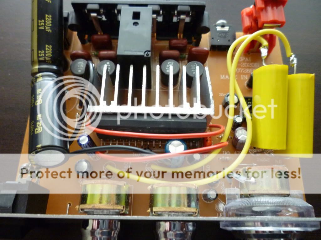
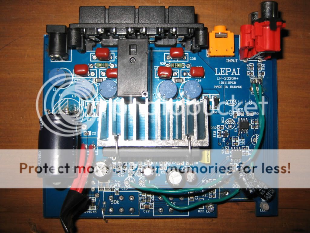
For bypassing the op-amp and tone controls, the photo below shows how I did it. After replacing the input caps (big yellow caps on the right), I left one side "floating" and then soldered on those yellow hookup wires, one for each channel. On the other end of these wires, I removed the pair of caps near the TA2020 chip (they are marked 2.2uF on the board, but 1.75uF were actually installed). I then soldered the yelloy hookup wires to the unshaded side of the solder pads where the caps were removed.
If and when I get time, I might look at changing the output inductors to toroids as others have reported better bass response.
I've learnt so much on these forums... thanks to all of you who contribute!
Cheers,
Pete
Nice post, Pete. I may try this as a winter project. I guess it's spring for you.
Oh yeah, I may be the one who mentioned the thump. That's good to hear that it's minimal.
Oh yeah, I may be the one who mentioned the thump. That's good to hear that it's minimal.
Purchased a Lepaï LP2020A+ amplifier. I'm satisfied with the amplifier, good sound, but I don't like the soft-start circuit: I explain why.....
when you turn up the power everything went well. No pop, no click noise, the relay works fine.
When you shut down the power supply, it's another story: I hear a HUGE pop 🙁
How to improve the soft start circuit in order to avoid a pop at shut-down of the unit ?
Regards.
Largol.
when you turn up the power everything went well. No pop, no click noise, the relay works fine.
When you shut down the power supply, it's another story: I hear a HUGE pop 🙁
How to improve the soft start circuit in order to avoid a pop at shut-down of the unit ?
Regards.
Largol.
Lepai LP-2020A+
A+ Version: Just got myself one of these and thought I'd take a look inside as I'm getting a little distortion at around 11 o/clock. See the attached picture of R29 (Nr Op Amp). It was totally shorted and not reading it's 10K across the points. It now is 🙂
I also found quite a few dry joints throughout and while it will work with these now, it may not down the road. I have re-touched more than a few using solder wick braid to clean joints where I had to. SMT work looks a bit iffy in general - rushed probably but I wasn't expecting much for the money 😉
I will have a hunt about for some better Op amps and may upgrade them if I still have the distortion.
I see the circuit board layout has allowed for bigger caps to be fitted on the imput - C32,33,36,38 positions. I'm not gonna mess with it too much though. Famous last words lol
Yes, very nice Pete. My two amps are still going stong, and I still think they sound fantastic!
Hey guys.
Just finished doing the first set of mods to the lepai. I don't have proper speakers right now where I am but testing on a spare driver with no box I think it is better 😉
I changed the 16v input cap to a 4700uf samwha SD series 25V cap, the output caps to 250V philips 0.47uf 5% caps and the stock inductors to 3A 10uh inductors. They are a straight coil with some stuff (ferrite?) inside. I placed them so that they point upwards. I wonder if this will make them interract in a bad way but whatever 😉 I have 50v 2,2uf film caps for the input decoupling, to install where the C30 and C31 caps are. Will buy some opa2134's off ebay (or ne5532). Just gotta remember to get the smd package this time 😀
The problem that has arisen is that the right output is noticeably louder 🙁
I measured a sine wave output with my multimeter and when the right channel is reading 2.03V the left one is only 1.53V..
Didn't check this before but I didn't notice it until now... Sort of bummed about this so does anyone have a known solution?
PS. pics will follow at some point 🙂
The volume potentiometer is a likely suspect. It might just be a bad spot in the pot tracking; measure a few times at different pot settings. Then...
You could jumper both channels across the volume control and see if things equal out. If so, then pot replacement or leaving it jumpered is one fix. Or (and this is a last resort "fix") you could keep the pot installed and tweak the op amp gain for one channel. I would wait until I finished the other mods to do this, though, after another balance check.
You could jumper both channels across the volume control and see if things equal out. If so, then pot replacement or leaving it jumpered is one fix. Or (and this is a last resort "fix") you could keep the pot installed and tweak the op amp gain for one channel. I would wait until I finished the other mods to do this, though, after another balance check.
I measured the volume pot resistance and the values were off. I'll probably end up buying an ALPS pot off ebay.
For now I'll try to not notice the 1 or 2 missing db's. I'll probably make a bigger case for it because the stock case just doesn't do the chip inside justice 🙂 I guess I could also add a resistor in series for the other channel if I use wires from pcb to pot.
Today I will switch the rca input caps to the 2,2uf MKT cap.
What I'm really trying to get my head around is whether to get ne5532's or opa2134. I have understood that the op2134 is a bit more "high end" and newer. Whatever I choose I will probably be very happy 🙂
Oh noes 🙁
I had just added the rca input caps. Sounded better than before and I was listening to some music while scanning ebay for opamps. I decided to try out how loud it could go with the mods.
It did really well and my ears were starting to hurt so I turned it down a bit and then all of a sudden no sound but I did hear the relay switch off.
Now it just lights up with no response at all from the speaker outputs, no pops from the relay either. Still getting 12v up to the relay so far.
Tracing this double layer SMD board isn't fun at all so I haven't tested the relay on its own yet. No ticking or anything when I turn it on (this was a problem on the old version?)
Triple posting because I can't see an edit button anywhere.
If I connect what is supposed to be grounded on the relay to ground I get the famous 1hz ticking out of the speakers. Neither fault nor sleep is at 5v, both 0v. Haven't measured while the ticking is happening but I guess that they will then be high.
I have the newest model (blue pcb) so if anyone knows how to disconnect the fault and sleep pins on my model it would help greatly 🙂
Don't know if it would work even then but I'm really sad that my great sounding lepai died so young 🙁
Hello
I've been following all the threads on this forum about tripath based amps and its been a hell of a trip on this very nice forum.
I love music and DIY but happens that i'm not so good with electronics 😱 .
So after alot of reading and searching I purchased some tripath boards and finished amps.
I received four TA2020A+ today and while I did purchased the old version with through hole components there is nothing I can do about that🙁.
Three of them worked out of the box and one was dead.I tried to look out for shorts, bad soldering and I even replaced caps but nothing changed.
Two units had awful bass and some hiss while the last one had a much better overall sound quality. I did opened that unit and the one with better sound had black capped inductors while the other two, blue. I don't know if the better sound quality is related to the different inductors but who knows.
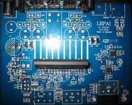
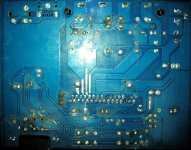
I know that many of us, lepai ta2020a+ owners want to bypass tone and or opamps and while I don't have the skills to trace the pcb and create a datasheet / find a solution I can always use the dead unit and get it almost naked and that's what I did.
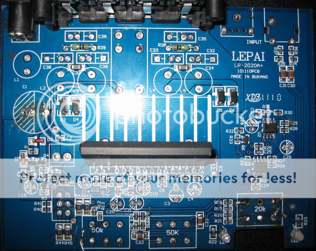

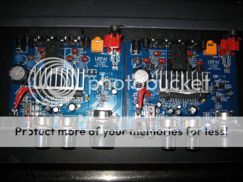
I hope it helps and if anyone happens to need a photo or details about a specific section of the pcb just ask, please. Bellow I attached some high res photos.
Thank you all.
I've been following all the threads on this forum about tripath based amps and its been a hell of a trip on this very nice forum.
I love music and DIY but happens that i'm not so good with electronics 😱 .
So after alot of reading and searching I purchased some tripath boards and finished amps.
I received four TA2020A+ today and while I did purchased the old version with through hole components there is nothing I can do about that🙁.
Three of them worked out of the box and one was dead.I tried to look out for shorts, bad soldering and I even replaced caps but nothing changed.
Two units had awful bass and some hiss while the last one had a much better overall sound quality. I did opened that unit and the one with better sound had black capped inductors while the other two, blue. I don't know if the better sound quality is related to the different inductors but who knows.
I know that many of us, lepai ta2020a+ owners want to bypass tone and or opamps and while I don't have the skills to trace the pcb and create a datasheet / find a solution I can always use the dead unit and get it almost naked and that's what I did.
I hope it helps and if anyone happens to need a photo or details about a specific section of the pcb just ask, please. Bellow I attached some high res photos.
Thank you all.
Attachments
Last edited:
So if took it right from what was wrote here and what the old version schematics shows. To bypass tone controls and op amps on the pcb 101110 (ta2020a+ ) one just needs to remove c30, c31, c20 and c21. and then connect c30 negative pad to c20 positive using coupling caps and do the same with c31 and c21 ? Do I need to cut traces or remove any other components ?
Thank You
Thank You
Last edited:
An engineer friend of mine looked at the schematic on this .PDF & pointed out the corresponding components on my PCB. He said it makes sense for the Amp manufacturers to just copy the Tripath diagram.
So are the schematics of the first & later A+ models the same? Is the only difference the components going surface mount?
http://www.e-ele.net/DataSheet/TA2020.pdf
So are the schematics of the first & later A+ models the same? Is the only difference the components going surface mount?
http://www.e-ele.net/DataSheet/TA2020.pdf
That's it.
I put my "dead" unit components on board again and gave it a try first connecting an vu meter to the outputs since I don't own a multimeter and the neddles responded as they should to the volume set and power. I did that to avoid blowing up my speakers in case everything was wrong
To bypass op amps and tone controls on TA2020a+ pcb 101110 you must remove c30, c31, c20 and c21.
Then just connect c31 positive to c21 positive and do the same with c30 and c20. Yes, the caps orientation for c20 and c21 are wrong printed on the pcb.
As you can see I used the same bipolar coupling caps that wer originally placed at c20 and c21. I have mundorfs, metal film, nichicons and new inductors on their way to my home already.
Shame on me for asking you guys how to bypass it. It needed only a look at the schemathic of the old lepai, the ta2020 datasheet for pinouts and ta2020a+ pcb. I feel ashamed for asking on how to do it.😱
Oh i'm pretty happy with the result. No clipping, no hiss I can increase the volume much further with the plesure of having a much better experience. I almost can't believe it is the same amp. I don't need op amps to play louder with the expense of heinous sound quality .
Forgive me if my english su*ks
Last edited:
A Question
What's the fascination with these? The price? They sure are cheap and they have improved the build quality over the years, but they still aren't great.
The 41Hz AMP6 is so much better that to me it would justify the small extra cost.
What's the fascination with these? The price? They sure are cheap and they have improved the build quality over the years, but they still aren't great.
The 41Hz AMP6 is so much better that to me it would justify the small extra cost.
What's the fascination with these? The price? They sure are cheap and they have improved the build quality over the years, but they still aren't great.
The 41Hz AMP6 is so much better that to me it would justify the small extra cost.
I guess it's also the learning experience that attracts. That was a factor for me when I was starting out. It's somewhat unfortunate that these amps are so very low-quality that they present a bad picture of Tripath amps.
I'll resoundingly second the Amp6. Those are re-li-a-ble, and sound unbelievably good. Out-bass, out-punch any bigger amp you'll ever have heard.
- Status
- Not open for further replies.
- Home
- Amplifiers
- Class D
- Lepai T-Amp with TA2020